Component installation, Integrated control panel, Junction panel – Toa FS-970 SERIES User Manual
Page 18
18
8. COMPONENT INSTALLATION
This section describes the points of installation you need to bear in mind when mounting the following main
components in the rack.
8.1. Integrated Control Panel
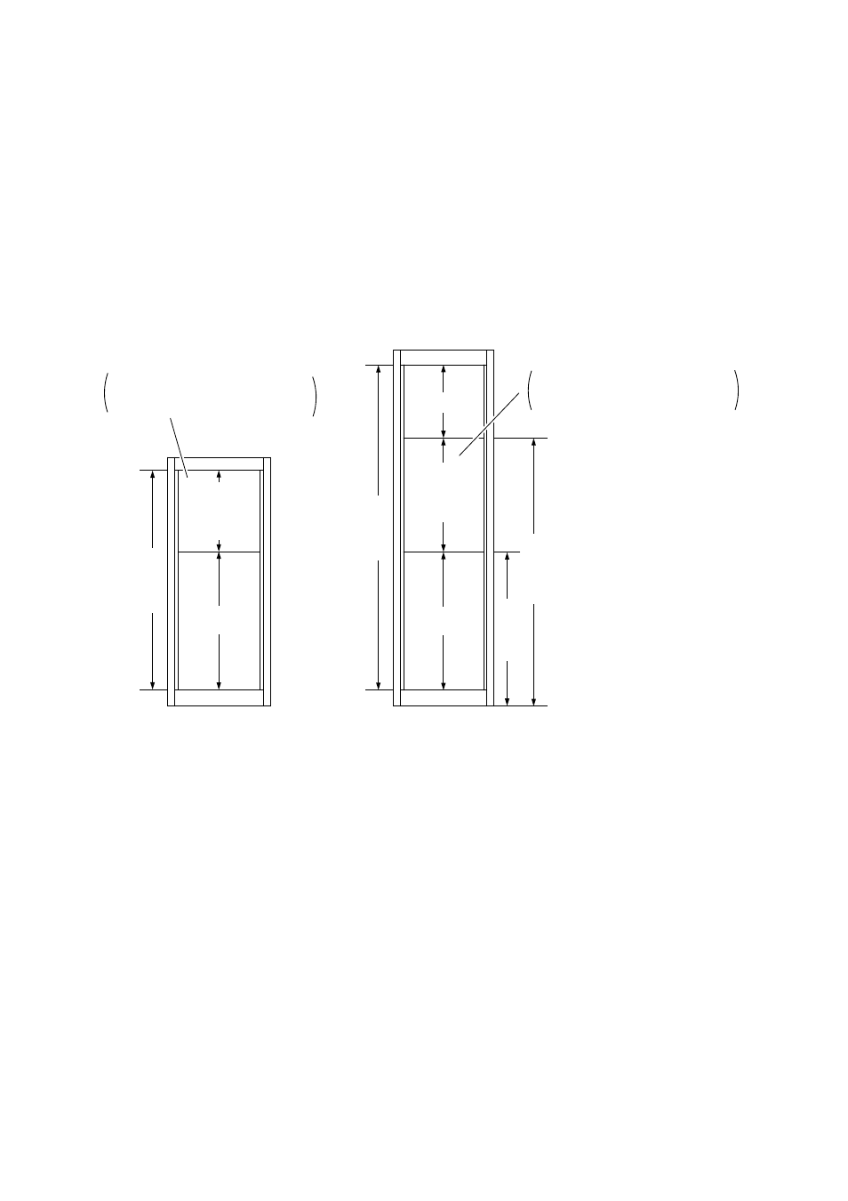
It is highly recommended that all the switches on the emergency operation panel be positioned at the height of
0.8 to 1.5 m from the floor. Therefore, the Integrated Control Panel EP-0510 and the Expansion Operation
Panels EP-029-10 and EP-029-20 must be positioned at the height shown below. When exceeding such
height ranges, install them in multiple racks and arrange those racks side by side.
Installation
height range
Under
10-unit size
Over
17-unit size
27-unit size
CR-272 rack
Capacity: 50 emergency broadcast zones
Installation
height range
Under
15-unit size
Over
17-unit size
Over 9-unit size
41-unit size
Over 0.8 m
Under 1.5 m
CR-412/-412-6 rack
Capacity: 110 emergency broadcast zones
One integrated control panel (5U) and
up to 2 expansion operation panels
(2U) are mountable.
One integrated control panel (5U) and
up to 5 expansion operation panels
(2U) are mountable.
The above figures show that the racks are installed directly on the floor. When using a channel base, ensure
that all the switches on the emergency operation panel are positioned at the height of 0.8 to 1.5 m from the
floor.
8.2. Junction Panel
• It is preferable to mount the perforated panel, such as the PF-023B, in the lowermost position of the rack,
and mount the Junction Panel JP-0410 above it. This facilitates connection of external wires.
• When mounting the Expansion Junction Panel JP-039-10 or JP-039-20 in the rack, mount it below the JP-
0410.