Using vector dynamics foundation systems – Tie Down Vector Dynamics Foundation System for Wind Zones lll User Manual
Page 17
D103
0
Tie Down Engineering
255 Villanova Drive SW
Atlanta, Georgia 30336
(404) 344-0000 • Fax (404) 349-0401
www.tiedown.com
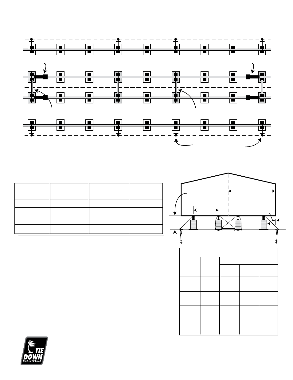
Example of a Double Section 28' x 72' Home
WIND ZONE I for Double Section Homes (High Pier Sets)
Using Vector Dynamics Foundation Systems
Soil Bearing Capacity: 1,000 PSF Minimum
Anchors Required:
30" with 2-4" helix anchors (#59095), 12" Stabilizer Plates (#59292)
& 1-1/4" frame tie with connector
Home Length
Vector Systems
Anchors Required
Longitudinal
Required
Per Side
System (LSD)*
0 to 48'
2
2
2 (4 Struts)
49' to 71'
3
3
2 (4 Struts)
72' to 84'
4
4
2 (4 Struts)
85' to 90'
5
5
2 (4 Struts)
NOTES:
Pier height is measured from top of the Vector Pad to the
bottom of the I-beam. Vector Systems should be spaced
as symmetrically as possible along the length of the home.
Pier spacing must be consistent with home manufacturers
instruction and/or state requirements.
Maximum allowable working load for metal strut: 3150 lbs.
* One Longitudinal Vector System is made up of 2
struts, which can be used separately.
Vector System
LSD
LSD
Vector System
Anchors &
Stabilizer Plates
Unit Width
See below
chart
I-Beam
Spacing
45˚
Min.
156”
156”
156”
164”
164”
164”
180” Min
180” Min
180” Min
140” Min
140” Min
140” Min
82.5”
95.5”
99.5”
82.5”
95.5”
99.5”
82.5”
95.5”
99.5”
82.5”
95.5”
99.5”
88”
70”
65”
98”
81”
76”
119”
101”
96”
66”
48”
43”
86”
69”
64”
96”
80”
74”
117”
100”
95”
64”
47”
42”
85”
68”
63”
95”
78.5”
73”
115”
99”
94”
64”
47”
42”
Wall Height & Trib
Max. Pier Height
7.0’
Trib=19’
7.5’
Trib=18’
8.0’
Trib=17’
Unit
Width
W
I-Beam
Spacing
IBS
Wind Zone I
17
Revised: 8/19/08