9 digital communication interface 37, 1 serial communications 37, 1 wiring 37 – ThermoWorks 9150-X HART SCIENTIFIC 9150 THERMOCOUPLE FURNACE User Manual
Page 37: 2 setup 37, Digital communication interface, Serial communications, Wiring, Setup, 9digital communication interface, 1 serial communications
9
Digital Communication Interface
The furnace is capable of communicating with and being controlled by other
equipment through the digital serial interface.
With a digital interface the instrument may be connected to a computer or other
equipment. This allows the user to set the set-point temperature, monitor the
temperature, and access any of the other controller functions, all using remote
communications equipment. Communications commands are summarized in
Table 2 on page 40.
9.1
Serial Communications
The calibrator is installed with an RS-232 serial interface that allows serial dig-
ital communications over fairly long distances. With the serial interface the user
may access any of the functions, parameters and settings discussed in Section 8
with the exception of the BAUD rate setting.
9.1.1
Wiring
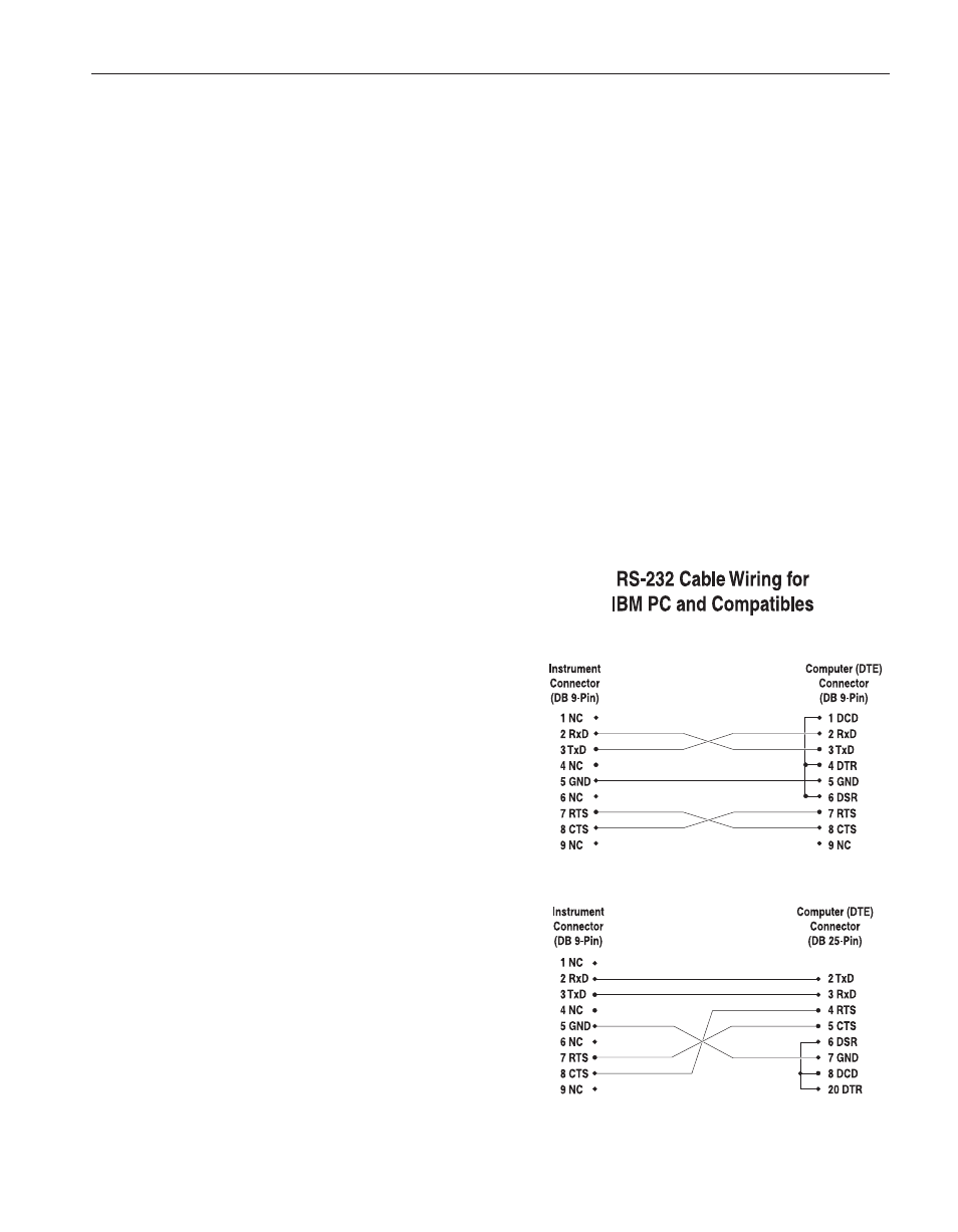
The serial communications ca-
ble attaches to the calibrator
through the DB-9 connector at
the back of the instrument. Fig-
ure 5 shows the pin-out of this
connector and suggested cable
wiring. The serial cable should
be shielded. If the unit is used
in a heavy industrial setting,
the serial cable must be limited
to ONE meter.
9.1.2
Setup
Before operation the serial in-
terface must first be set up by
programming the BAUD rate
and other configuration param-
eters. These parameters are
programmed within the serial
interface menu. The serial in-
terface parameters menu is out-
lined in Figure 4 on page 22.
To enter the serial parameter
programming mode first press
“EXIT” while pressing “SET”
and release to enter the second-
37
9 Digital Communication Interface
Serial Communications
Figure 5 Serial Cable Wiring Diagram