Tj44e, Figure 1-1: system diagram, 053-uk – TeeJet 744E AUTO BOOM SECTION CONTROL User Manual
Page 5: Part number is dependent on kit contents
3
020-053-UK
TJ44E
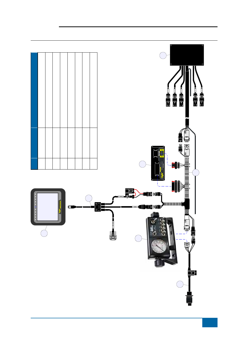
Figure 1-1: System Diagram
R
eg
ul
at
io
n
S1
S2
S3
M
as
te
r
1
1
1
1
1
2
2
2
2
2
10
08
-0
22
4
B
B
A
A
A
B
xx
x-
xx
x
xx
yy
xx
B
A
1
2
3
4
5
6
7
Pos.
Part #
Description
1
90-xxxxx*
Matrix Guidance Controller
2
45-05626
Power/CAN/Data Cable, Matrix
3
75-50061
TJ744E Sprayer Control, 5 sections
4
45-05789
Power Cable for
TJ744E incl. COBO con.
5
78-05072
Section Driver Module
6
198-396
TJ744E
ABSC Cable, 5 sec.
7a
199-370
TJ744E Harnes for
ARAG Manifold, 5 sec.
7c
45-10134
TJ744E Harnes for
TJ430 Manifold, 5 sec.
*Part number is dependent on kit contents
See also other documents in the category TeeJet Computers:
- Sentry 6140 (16 pages)
- 801 flowmeter (2 pages)
- GPS Speed Sensor (2 pages)
- IC18 SPREADER JOB COMPUTER (47 pages)
- IC18 SPREADER JOB COMPUTER (32 pages)
- IC18 SPRAYER JOB COMPUTER (43 pages)
- IC18 SPRAYER JOB COMPUTER (68 pages)
- IC18 NH3 JOB COMPUTER (63 pages)
- BOOMPILOT JOB COMPUTER (21 pages)
- BOOMPILOT JOB COMPUTER (32 pages)
- MATRIX 570VT Software version 1.00 (12 pages)
- MATRIX 570VT Software version 1.00 (20 pages)
- MT 600 Piston Injection Pump (6 pages)
- BoomPilot (2 pages)
- BoomPilot Pro Metric (2 pages)
- BoomPilot Pro (2 pages)
- 500 SLURRY COMPUTER (30 pages)
- 70 Series Speed Area Monitor (2 pages)
- 70 Series EPC - Manual Pump (4 pages)
- 70 Series Fill Flow (2 pages)
- 70 Series Flow Volume Monitor (2 pages)
- ARC-6000 (50 pages)
- TASC-6000 (78 pages)
- TASC-6100 (86 pages)
- TASC-6200 (50 pages)
- TASC-6200 (45 pages)
- TASC DATA LOGGER (17 pages)
- TASC PRINTER MODULE (8 pages)
- TASC-6000 Supplement (9 pages)
- 744A Sprayer Control (14 pages)
- 744E SPRAYER CONTROL (16 pages)
- 814-AB Airblast Sprayer Monitor (15 pages)
- 834 Sprayer Control (15 pages)
- 834 Sprayer Control L2.12 (15 pages)
- 834-P Sprayer Control (18 pages)
- 844 Sprayer Control (44 pages)
- 844 Operations Mini (2 pages)
- 844-AB Sprayer Control (24 pages)
- 844-E Sprayer Control (36 pages)
- 844-R Speed Compensated Application Control (32 pages)
- 854 Sprayer Control (52 pages)
- 026 – 73 AddFlow (8 pages)
- LH 3000 (24 pages)
- LH 4000 (44 pages)