TeeJet MT 600 Piston Injection Pump User Manual
Page 2
98-05086
R1
98-05086
R1
2
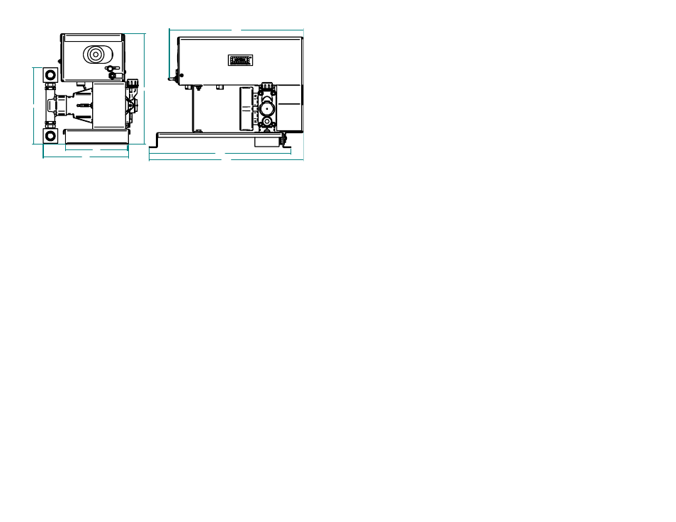
14.63
15.91
11.43
8.80
6.40
7.91
14.00
Fig. 2: Side Template
NOTE: Secure each pump firmly to eliminate vibration and possible
damage to the connecting hoses and cables.
P
LUMBING
See the sample plumbing diagram on page 6 for suggestions on how to
plumb the system.
C
ABLING
Each MT600 injection pump comes with two cables, a pump control cable
and a pump power cable. See the sample system diagrams on pages 7 and 8
for suggestions on how the system should be connected.
Route all cables carefully, avoiding moving parts, excessive heat and
exposure to tree limbs, stubble, or other debris. Allow enough slack at
all pivot points to prevent pinching or stretching the cables.
Secure the cables in place with cable fasteners and/or cable clamps.
Pump Control Cables: When the injection pumps have been designated
#1 , #2, etc., Midwest Technologies suggests the cable tags be marked
accordingly (use a permanent ink - water proof marker). Carefully route the
cable to the console (TASC system) or Product Control Module (Legacy
system).
Pump Power Cable: Route each power cable to the vehicle battery (12
VDC only). Attach the red lead (fused) to the positive post and the black
lead to the negative post of the battery.
NOTES
11