Draw line zones – SmarTek Systems SVS-1 User Guide-Part E User Manual
Page 6
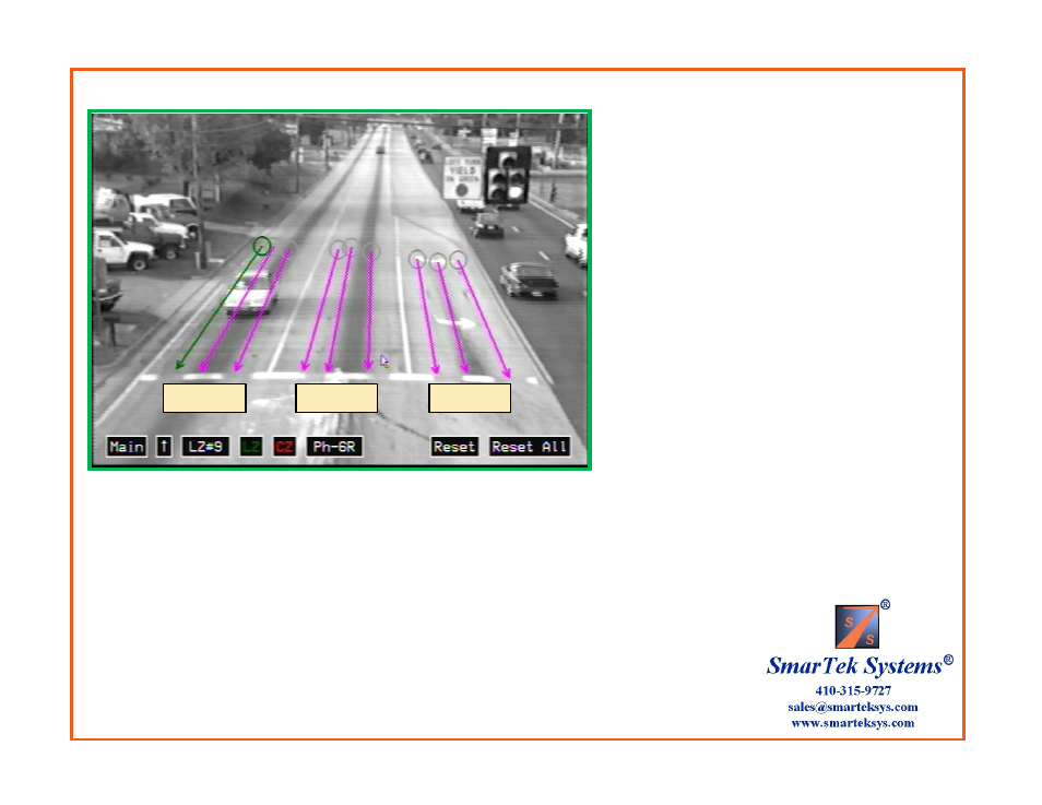
Draw Line Zones
Phase assignment Codes:
Ph-1L
Ph-6T
Ph-6R
Ph-3L
Ph-8T
Ph-8R
Ph-5L
Ph-2T
Ph-2R
Ph-7L
Ph-4T
Ph-4R
Ph-9L
Ph-14T
Ph-14R
Ph-11L
Ph-16T
Ph-16R
Ph-13L
Ph-10T
Ph-10R
Ph-15L
Ph-12T
Ph-12R
After drawing all line zones and grouping
by phase, click the “Main” button to return
to the Main Setup Display.
Phase 1L
Phase 6R
Phase 6T
SVS-1 detection is directional, hence be sure
the direction arrow on each line zone is
pointed in the correct direction of travel.
L designates Left Turn Lane
T designates Thru Lane
R designates Right Turn Lane
Note: The “T” and “R” designation allows for later
applying detection delay and/or extension to the right
turn and/or thru lanes before combining them into one relay.
The “Up” arrow beside the “Main” button
provides for moving the setup buttons to the
top of the image if they are in in the way of
drawing line zones. After moving the setup
buttons to the top, the “Up” arrow becomes
a “Down” arrow.
The selected line zone is shown in green, all
others are shown in magenta (show in output
video) or gray (not show in output video).
Clicking in the upper/lower part of the button field will increment/decrement the value or
the selection.