SmarTek Systems SVS-1 User Guide-Part E User Manual
Page 24
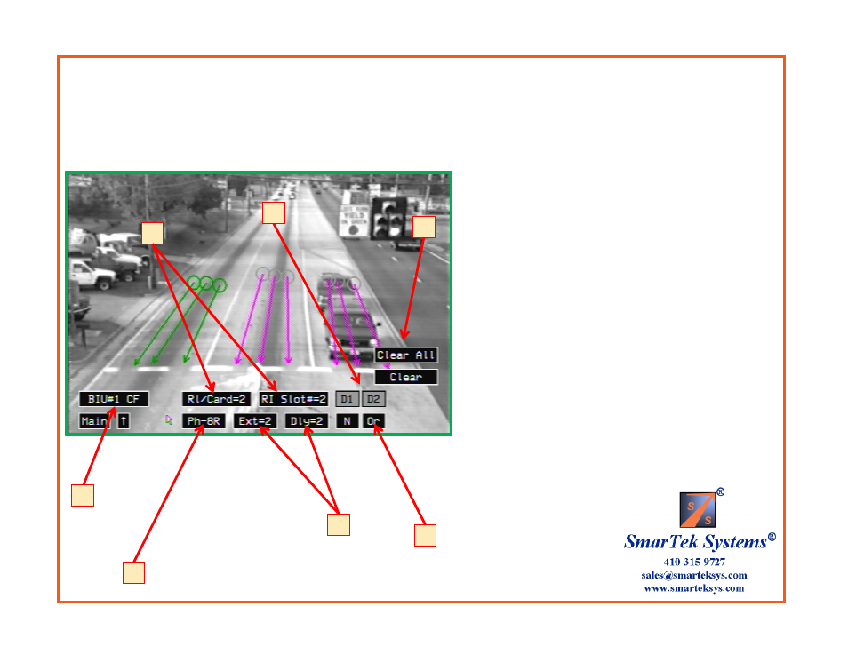
Scenario 5 (Con’t) Set 2 Output Relays to BIU #1 Card File
Select Detector Interface and Route Relays:
1) Click the Detector Interface button to select the type
of detector/controller interface to be used ( BIU #1 Card
File ).
2) Click the Ph- button to select Phase group 8R. Note
that the line zones corresponding to the selected phase
group turn green. All others are magenta.
3) Click the RI/Card= button to select the number of
relays per card = 2 . Click the RI Slot= to select the card
file slot used= 2.
4) After selecting the RI/Card=2 and the RI Slot=2, the
number detector channels (D1, D2, etc.) that are shown
changes corresponding to this selection.
5) Click the Ext= and the Dly= to select the Detection
Extension in seconds and the Detection Delay in seconds.
6) Click N, Or, And button to select logic for combining
(N=Not Used) Phase Groups into Detector Channels.
7) To clear the settings for the selected Phase group or
for all Phase groups click the Clear or the Clear All
button.
6
1
2
3
4
7
5
BIU #1 Card file Detector/Controller Interface with 2 Relays per SVS-1 card, Slot 2 used, and 3 Phases (Line Zone Groups)
Phase 3L, Detection Delay=0 sec, Detection Extension=0, Route to Detector Channel D1
Phase 8T, Detection Delay=0 sec, Detection Extension=0, Route to Detector Channel D2
Phase 8R, Detection Delay=2 sec, Detection Extension=2, Route to Detector Channel D2