SmarTek Systems SVS-1 User Guide-Part E User Manual
Page 11
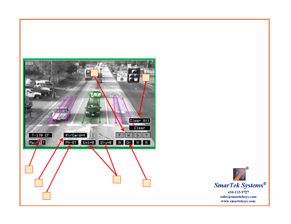
Scenario 1 (Con’t) Set 4 Output Relays For a Type 170/2070 Card File Interface
Select Detector Interface and Route Relays:
1) Click the Detector Interface button to select the type
of detector/controller interface to be used ( Type-170 ).
2) Click the Ph- button to select Phase group 6T. Note
that the line zones corresponding to the selected phase
group turn green. All others are magenta.
3) Click the RI/Card= button to select the number of
relays per card = 4 .
4) After selecting the RI/Card=4, the number card edge
relays (F, W, etc.) that are shown changes corresponding
to this selection.
5) Click the Ext= and the Dly= to select the Detection
Extension in seconds and the Detection Delay in seconds.
6) Click N, Or, And button to select logic for combining
(N=Not Used) Phase Groups into Card Edge Relays.
7) To clear the settings for the selected Phase group or
for all Phase groups click the Clear or the Clear All
button.
6
1
2
3
4
7
5
Type-170 Detector/Controller Interface with 4 Relays per SVS-1 card and 3 Phases (Line Zone Groups)
Phase 1L, Detection Delay=0 sec, Detection Extension=0, Route to Card Edge F
Phase 6T, Detection Delay=0 sec, Detection Extension=0, Route to Card Edge W
Phase 6R, Detection Delay=2 sec, Detection Extension=0, Route to Card Edge W