Draw line zones – SmarTek Systems SVS-1 User Guide-Part E User Manual
Page 5
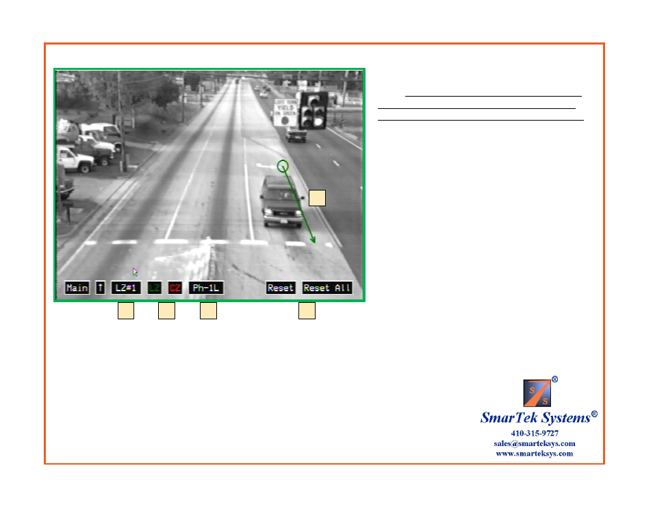
Draw Line Zones
Set Line Zone Position, Size and Phase Group:
1) Click the LZ# button to select the line zone to
draw. If the previous line zone has been assigned a
phase, right clicking anywhere on the display will
assign that phase to the currently selected line zone.
2) Draw the Line Zone position by left clicking (hold
down left button) at the down road end of the Line
Zone and drawing the Line Zone to the up road end (at
this end, release the left button).
3) Click the LZ and CZ buttons to show (
green
) or
not show (
red
) the line zone and/or the circle zone in
the output video monitor signal.
4) Click the Ph- to assign the selected line zone to a
specific phase (i.e. LZs 1, 2, and 3 may be assigned to
phase 1L if they are in the Left Turn lane).
5) Repeat steps 1 thru 4 to set as many zones as is
needed. Each lane should have multiple Line/Circle
Zones.
6) To reset the selected line zone or all line zones,
click the Reset or Reset All button respectively.
Steps 1 thru 4 may be repeated as many times as
necessary until the position, size, and assignments
are satisfactory.
Phase assignment Codes:
6
1
2
3
4
Ph-1L
Ph-6T
Ph-6R
Ph-3L
Ph-8T
Ph-8R
Ph-5L
Ph-2T
Ph-2R
Ph-7L
Ph-4T
Ph-4R
Ph-9L
Ph-14T
Ph-14R
Ph-11L
Ph-16T
Ph-16R
Ph-13L
Ph-10T
Ph-10R
Ph-15L
Ph-12T
Ph-12R
L designates Left Turn Lane
T designates Thru Lane
R designates Right Turn Lane
Note: The “T” and “R” designation allows for later
applying detection delay and/or extension to the right
turn and/or thru lanes before combining them into one relay.
Clicking in the upper/lower part of the button field will increment/decrement the value or
the selection.