SilentKnight SK-Control-6 Six Circuit Notification Module User Manual
Page 6
SK-460-006
6
I56-3437-002
©2009 Honeywell International Inc.
C0247-03
BASE
ADDRESS
NAC
PS
NAC
PS
— +
+ —
NAC
PS
— +
+ —
NAC
PS
— +
+ —
NAC
TOP
BOT
– +
+ NAC –
– +
– PS +
SLC
PS
— +
+ —
+1
+2
+3
+4
+5
A
A
T11
T10
T0
+0
T12
T1
T2
T3
T4
T5
T13
T14
T15
T16
ENABLE POWER SUPPLY MONITOR
DISABLE SHORT CIRCUIT PROTECTION
— +
+ —
A/B SELECT
DISABLE
1
DISABLE
2
DISABLE
3
0
1
2 3 4 5
6
7
8
9
0
7
8
6
5
4
3
2
1
9
BASE
ADDRESS
NAC
PS
NAC
PS
— +
+ —
NAC
PS
— +
+ —
NAC
PS
— +
+ —
NAC
TOP
BOT
– +
+ NAC –
– +
– PS +
SLC
PS
— +
+ —
+1
+2
+3
+4
+5
T11
T10
T0
+0
T12
T1
T2
T3
T4
T5
T13
T14
T15
T16
ENABLE POWER SUPPLY MONITOR
DISABLE SHORT CIRCUIT PROTECTION
— +
+ —
A/B SELECT
DISABLE
1
DISABLE
2
DISABLE
3
0
1
2 3 4 5
6
7
8
9
0
7
8
6
5
4
3
2
1
9
EXTERNAL
POWER
SUPPLY
+
–
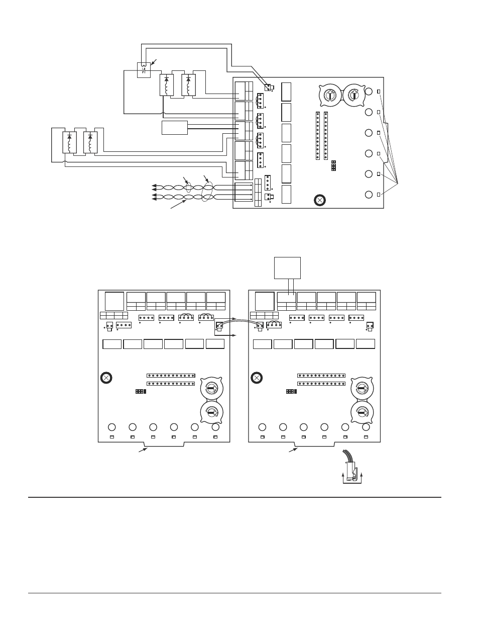
PCB 2
PCB 1
VIEW A-A
10
11
12
13
14
15
10
11
12
13
14
15
FIGURE 10: ExAMPLE OF MULTIPLE BOARDS ShARING SAME
ExTERNAL SUPPLY.
Supply is shared by NACs +0 and +1 (on PCB 1) as well as +3, +4, and
+5 (on PCB 2). Refer to figures 9–12 for typical NAC wiring. Make certain lip
on long power supply jumper engages retaining tab on T10 or T16 as shown
in View A-A.
FCC STATEMENT
This device complies with part 15 of the FCC Rules. Operation is subject to the following two conditions: (1) This device may not cause harmful interference, and (2) this device must
accept any interference received, including interference that may cause undesired operation.
NOTE: This equipment has been tested and found to comply with the limits for a Class B digital device, pursuant to Part 15 of the FCC Rules. These limits are designed to provide
reasonable protection against harmful interference in a residential installation. This equipment generates, uses and can radiate radio frequency energy and, if not installed and used
in accordance with the instructions, may cause harmful interference to radio communications. However, there is no guarantee that interference will not occur in a particular installa-
tion. If this equipment does cause harmful interference to radio or television reception, which can be determined by turning the equipment off and on, the user is encouraged to try
to correct the interference by one or more of the following measures:
– Reorient or relocate the receiving antenna.
– Increase the separation between the equipment and receiver.
– Connect the equipment into an outlet on a circuit different from that to which the receiver is connected.
– Consult the dealer or an experienced radio/TV technician for help.
BASE ADDRESS
STATUS
INDICATORS
NAC
PS
NAC
PS
—
+
+
—
NAC
PS
—
+
+
—
NAC
PS
—
+
+
—
NAC
TO
P
BOT
–
+
+
NA
C
–
–
+
–
PS
+
SLC
PS
—
+
+
—
+1
+2
+3
+4
+5
T1
1
T10
T0
+0
T12
T1
T2
T3
T4
T5
T13
T14
T15
T16
ENABLE POWER SUPPL
Y
MONIT
OR
DISABLE SHO
R
T
CIRCUIT
PROTECTION
—
+
+
—
A/B SELECT
DISABLE 1
DISABLE 2
DISABLE 3
0
1
2
3
4
5 6
7 8 9
0
7 8
6
5
4
3
2
1
9
REMOVE SHUNT FOR CLASS A.
TO NEXT
DEVICE
–
+
–
+
FROM PANEL OR
PREVIOUS DEVICE
–
+
–
+
SIGNAL LINE CIRCUIT (SLC) 32 VDC MAX.
SEE PANEL INSTRUCTION MANUAL
FOR WIRE REQUIREMENTS.
(–)
(+)
POWER-LIMITED
AND SUPERVISED
TOP OF T0
EOLR-1
(TYP)
RED
VIO
VIO
RED
BLK
BLK
(–)
(+)
EXTERNAL
POWER
SUPPLY
+
–
(–)
(+)
(–)
(+)
10
11
12
13
14
15
C0178-04
FIGURE 9: ExAMPLE OF CLASS A, STYLE Z NAC CONFIGURATION wITh A SINGLE SUPPLY ShARED BY 2 NACS.