Base address address disable – SilentKnight SK-Control-6 Six Circuit Notification Module User Manual
Page 2
SK-460-006
2
I56-3437-002
TABLE 1: ShORT CIRCUIT PROTECTION - UL 864 9Th EDITION REqUIREMENTS
NOTICE TO USERS, INSTALLERS, AUTHORITIES HAVING JURISDICTION, AND OTHER INVOLVED PARTIES
This product incorporates field-programmable software. In order for the product to comply with requirements in the Standard for Control
Units and Accessories for Fire Alarm Systems, UL 864, certain programming features or options must be limited to specific values or not used
at all as indicated below.
Program Feature or Option
Permitted in
UL 864 (Y/N)
Possible Settings
Settings Permitted in UL 864
Disabling short circuit protection
when a single power supply is
shared by multiple NACs
No
Enable or Disable short
circuit protection
Enable short circuit protection when a single power sup-
ply is shared by multiple NACs. Short circuit protection
can be disabled only when a power supply is not shared by
multiple NACs.
COMPATIBILITY REqUIREMENTS
To ensure proper operation, this module shall be connected to a compatible
Silent Knight system control panel.
COMPONENTS
The following is a description of the SK-Control-6 mounting framework:
One or two SK-Control-6 modules can be installed in a IDP-ACB cabinet.
•
The IDP-ACB cabinet has a built-in chassis that will accommodate one or two
SK-Control-6 modules.
0
1
2 3 4 5 6
7
8
9
0
7
8
6
5
4
3
2
1
9
10
11
12
13
14
15
BASE
ADDRESS
ADDRESS
DISABLE
0
1
2 3 4 5 6
7
8
9
0
7
8
6
5
4
3
2
1
9
BASE
ADDRESS
ADDRESS
DISABLE
10
11
12
13
14
15
The front SK-Control-6 module positions of each chassis are offset below the
rear SK-Control-6 module positions so that all of the status indicators are vis-
ible. For cabinet dimensions refer to the IDP-ACB instruction manual.
INSTALLATION STEPS
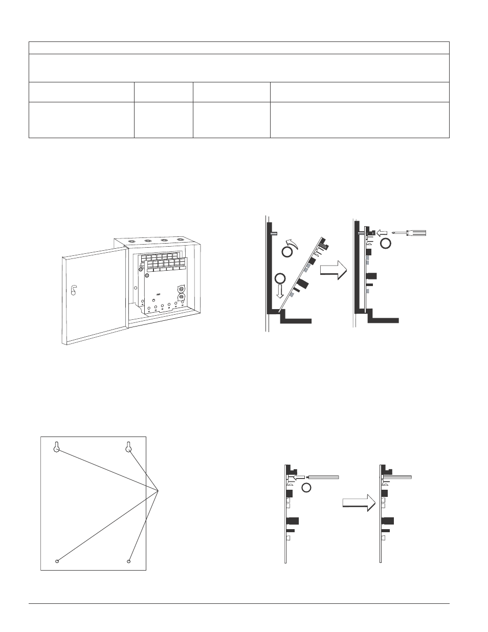
1. Cabinet Mounting
In a clean, dry area, mount the backbox using the four holes provided in the
back surface of the cabinet (Figure 3).
FIGURE 1: IDP-ACB CABINET
FIGURE 2: TYPICAL MOUNTING hOLE LOCATIONS
BACKBOX
MOUNTING
HOLES
C0235-00
C0234-03
2. Module Installation
There are two methods for installing a module in the rear position of a
chassis. Method one is for installation of a rear module only, when no
module will be installed in front of it. Refer to Figure 3 for instructions.
Method two is for installation of a rear module when another module
will be installed in the chassis position in front of it. Refer to Figures 4a
and 4b for method two. All necessary screws and standoffs are supplied
with the modules.
2
3
1
Step 1:
Insert the bottom of the SK-Control-6 module down into a rear slot
on the chassis.
Step 2:
Carefully swing the upper edge of the board back towards the back
of the chassis until it touches the two standoffs.
Step 3:
Align two 4-40 screws with the two standoffs and tighten.
Step 4:
Address and wire the modules according to the instructions in this
manual.
The steps in Figures 4a and 4b describe and illustrate module installation
when the rear chassis position and the position in front of it will be filled.
Front position installation is possible only if the rear position is filled with a
module.
C0237-00
FIGURE 3: INSTALLATION OF REAR MODULE ONLY, METhOD ONE
1
C0225-00
FIGURE 4A: INSTALLATION OF SK-CONTROL-6 MODULE IN A REAR
ChASSIS POSITION, METhOD TwO