SilentKnight SK-Control-6 Six Circuit Notification Module User Manual
Page 4
SK-460-006
4
I56-3437-002
POwER SUPPLY wIRING AND SUPERVISION
Table 3 gives an overview of how the power connectors, T0–T5 and T10–T15,
are interconnected by the circuit board (PCB). The external supply connection
points, at T0–T5, are marked by PS– and PS+ on the PCB legend. Pin 1 is
indicated by a dot next to T10–T16. The odd pins, on T10–T16, always con-
nect to PS– pins (e.g. PS–, of the +0 NAC, is connected to T10–1 and T11–1).
The even pins always connect to PS+ pins (e.g. PS+, of the +5 NAC, is con-
nected to T15-4 and T16-2).
TABLE 3
PS OR NAC NUMBER (TERMINAL / PINS)
TERMINAL / PINS
+0 (T0 – BOTTOM / PS- & PS+)*
T10 / 1 & 2, T11 / 1 & 2
+1 (T1 / PS- & PS+)
T11 / 3 & 4, T12 / 1 & 2
+2 (T2 / PS- & PS+)
T12 / 3 & 4, T13 / 1 & 2
+3 (T3 / PS- & PS+)
T13 / 3 & 4, T14 / 1 & 2
+4 (T4 / PS- & PS+)
T14 / 3 & 4, T15 / 1 & 2
+5 (T5 / PS- & PS+)
T15 / 3 & 4, T16 / 1 & 2
*Note: T0–TOP is reserved for SLC connections only (see Figure 5).
All power supplies, external to the cabinet (in which the SK-Control-6 is
housed), should be connected to T0–T5 which are suitable connectors for
field wiring. The 1 x 4 terminal blocks, shown on page 1, should be used to
make these connections.
All NACs can be wired to be powered by separate external supplies (figures
6 and 8 are typical), or a single supply (figures 7 and 9 are typical) can be
shared among multiple NACs. If a supply is to be shared, between NACs wired
to a common PCB, use the short power supply jumpers shown on page 1.
The jumpers can be used on T11–T15. Refer to Table 4 for jumper functions.
When multiple (2 or more) NAC circuits share a power supply, the wiring for
the power supply must be in conduit and 20 feet or less from the SK-Control-6
board.
BASE ADDRESS
STATUS
INDICATORS
NAC
PS
NAC
PS
—
+
+
—
NAC
PS
—
+
+
—
NAC
PS
—
+
+
—
NAC
TO
P
BOT
–
+
+
NA
C
–
–
+
–
PS
+
SLC
PS
—
+
+
—
+1
+2
+3
+4
+5
T1
1
T10
T0
+0
T12
T1
T2
T3
T4
T5
T13
T14
T15
T16
ENABLE POWER SUPPL
Y
MONIT
OR
DISABLE SHO
R
T
CIRCUIT
PROTECTION
—
+
+
—
A/B SELECT
DISABLE 1
DISABLE 2
DISABLE 3
0
1
2
3
4
5 6
7 8 9
0
7 8
6
5
4
3
2
1
910
11
12
13
14
15
EXTERNAL
POWER
SUPPLY
TO NEXT
DEVICE
–
+
–
+
FROM PANEL OR
PREVIOUS DEVICE
–
+
–
+
SIGNAL LINE CIRCUIT (SLC) 32 VDC MAX.
SEE PANEL INSTRUCTION MANUAL
FOR WIRE REQUIREMENTS.
(–)
(+)
POWER-LIMITED
AND SUPERVISED
TOP OF T0
EOLR-1
RED
VIO
VIO
RED
BLK
BLK
(–)
(+)
+
–
47K
TABLE 4
JUMPER LOCATION
NAC PAIR SHARING SUPPLY
T11*
+0 and +1
T12
+1 and +2
T13*
+2 and +3
T14
+3 and +4
T15*
+4 and +5
*NOTE: Jumpers must be placed on T11, T13 and T15 for all Class A, Style Z
applications.
A supply can be wired to be shared among multiple PCBs in the same cabinet
(figure 10 is typical). To share among multiple PCBs: use the long power sup-
ply jumpers (shown on page 1) to connect either T10 or T16, of one PCB, to
either T10 or T16 of the other PCB..
An EOL relay must be used for every external power supply (figures 6–9 are
typical). The EOL relay coil should always be connected at the external power
supply input of the module which is connected to the ends of the wires which
are farthest from the power supply. The EOL relay contacts should always be
connected in series with the NAC wiring of the same module. The EOL relay
coil should be connected across the PS+ (red wire) and PS- (black wire) if
it is connected at T0 – T5. The EOL relay coil should be connected across
adjacent pins (red – even pin#, black – odd pin#), of the same connector, if
T10 – T16 are used. If the supply is an audio amplifier then the points, where
the EOL relay coil would normally be connected, should be connected to the
amplifier supervision EOL device (figure 10 is typical).
All wiring must be in accordance with the NEC, NFPA 72 and all other ap-
plicable codes and standards. All external power supplies must be voltage
regulated with battery back-up. All external power supplies, audio amplifiers,
EOL relays, and notification appliances must be UL listed for fire protection
signaling applications.
*NOTE 1: EOL Relay Coil Connections must be made using EOL Relay Con-
nector Assemblies on T10–T16 in event that all NACs on the PCB have dedi-
cated supplies.
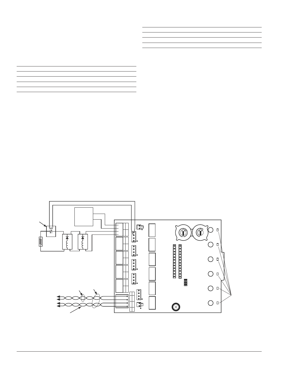
FIGURE 6: ExAMPLE OF CLASS B, STYLE Y NAC CONFIGURATION wITh A SINGLE SUPPLY DEDICATED TO A SINGLE NAC.
C0176-05