SilentKnight B224RB 6 Mounting Base w/Built-in Relay User Manual
Page 3
D250-03-00
3
I56-2815-000R
C0890-00
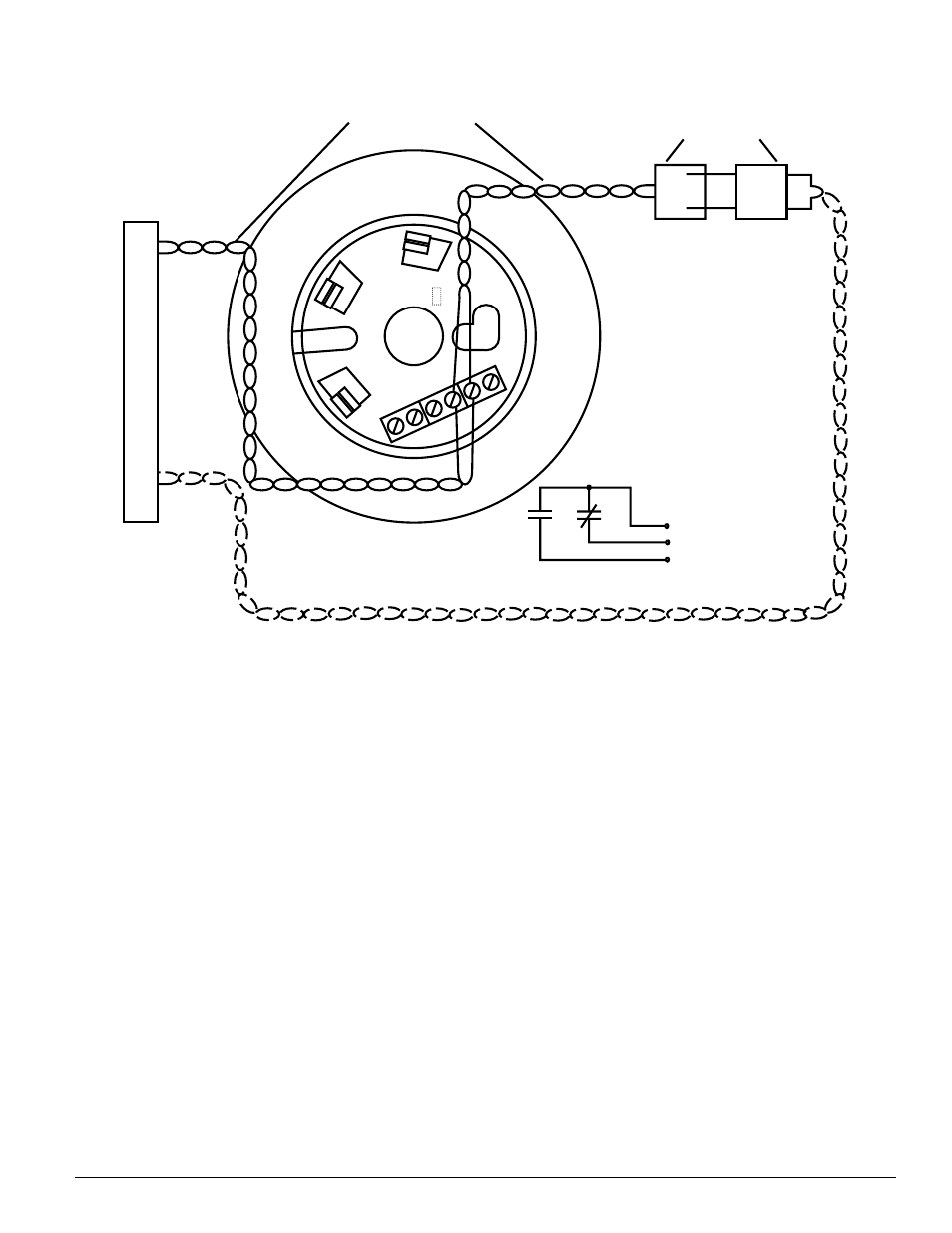
LISTED COM
P
A
TIBLE CONTRO
L
P
ANEL
CLASS A OPTIONAL WIRING
3 RELAY COMMON
1 NORMALLY CLOSED
2 NORMALLY OPEN
TWISTED PAIR RECOMMENDED
(+)
(–)
(+)
(–)
1
(N.C.)
2
(N.O.)
3
(COMMON)
4
(+)
5
(–)
6
(S)
OTHER INTELLIGENT
DEVICES
•
LONG DELAY
•
SHORT DELAY
•
Figure 2. Wiring diagram:
Tamper-resist Feature
NOTE: Do not use the tamper-resist feature if the removal
tool is to be used.
This detector base includes a tamper-resist feature that pre-
vents its removal from the base without the use of a tool.
To activate this feature, break the tab from the detector base as
shown in Figure 3A (see page 4). Then, install the detector.
To remove the detector from the base once the tamper-re-
sist feature has been activated, insert a small-bladed screw-
driver into the slot in the side of the base and push the
plastic lever away from the detector head (see Figure 3B,
page 4). This allows the detector to be rotated counter-
clockwise for removal.
NOTE: Head removal after the tamper-resist feature has
been activated first requires removal of the decorative ring.
The tamper-resist feature can be defeated by breaking and
removing the plastic lever from the base. However, this pre-
vents the feature from being used again.