SilentKnight B224RB 6 Mounting Base w/Built-in Relay User Manual
Page 2
D250-03-00
2
I56-2815-000R
Installation Guidelines
All wiring must be installed in compliance with all appli-
cable local codes and any special requirements of the local
authority having jurisdiction, using the proper wire sizes.
The conductors used to connect smoke detectors to control
panels and accessory devices should be color-coded to re-
duce the likelihood of wiring errors. Improper connections
can prevent a system from responding properly in the event
of a fire.
For signal wiring (the wiring between interconnected de-
tectors), it is recommended that the wire be no smaller
than 18 gauge (0.9 square mm). However, wire sizes up to
14 gauge (2.0 square mm) can be used with the base. The
use of twisted pair wiring or shielded cable for the power
(+ and –) loop is recommended to minimize the effects of
electrical interference.
If shielded cable is used, the shield connection to and from
the detector must be continuous by using wire nuts, crimp-
ing, or soldering, as appropriate, for a reliable connection.
Alarm system control panels have specifications for allow-
able loop resistance. Consult the control panel specifica-
tions for the total loop resistance allowed before wiring the
detector loops.
Wiring Instructions
WARNING
The base uses a latching relay that can change states if it is
subjected to mechanical shocks or jarring. As a result, even
though relay contacts are in the open state when the base
is shipped from the factory, the contacts may have closed
during shipment.
Connecting an auxiliary control circuit to closed relay con-
tacts can cause an unexpected, and possibly dangerous,
activation of that circuit. Therefore, do NOT connect an
auxiliary control circuit to the relay contacts (terminals 1,
2, and 3) before ensuring that the relay contacts are in their
open state. Ensure that the contacts are open by applying
power to the bases WITHOUT the sensor heads installed.
Make wiring connections by stripping about
3
⁄
8
″ (10 mm) of
insulation from the end of the wire. Then, slide the wire un-
der the clamping plate and tighten the clamping plate screw.
Wire the normally open (NO) line to terminal 2 (see Fig-
ure 2). Insert the normally closed (NC) line of the relay to
terminal 1 and the relay common line to terminal 3. Wire
the communication lines in (+) and out (+)to terminal 4.
Insert the communication line in (–) and out (–) to terminal
5. Terminal 6 is for shielded cable only (see Figure 2). If
shielded cable is used, the shield connection to and from the
detector must be continuous by using wire nuts, crimping,
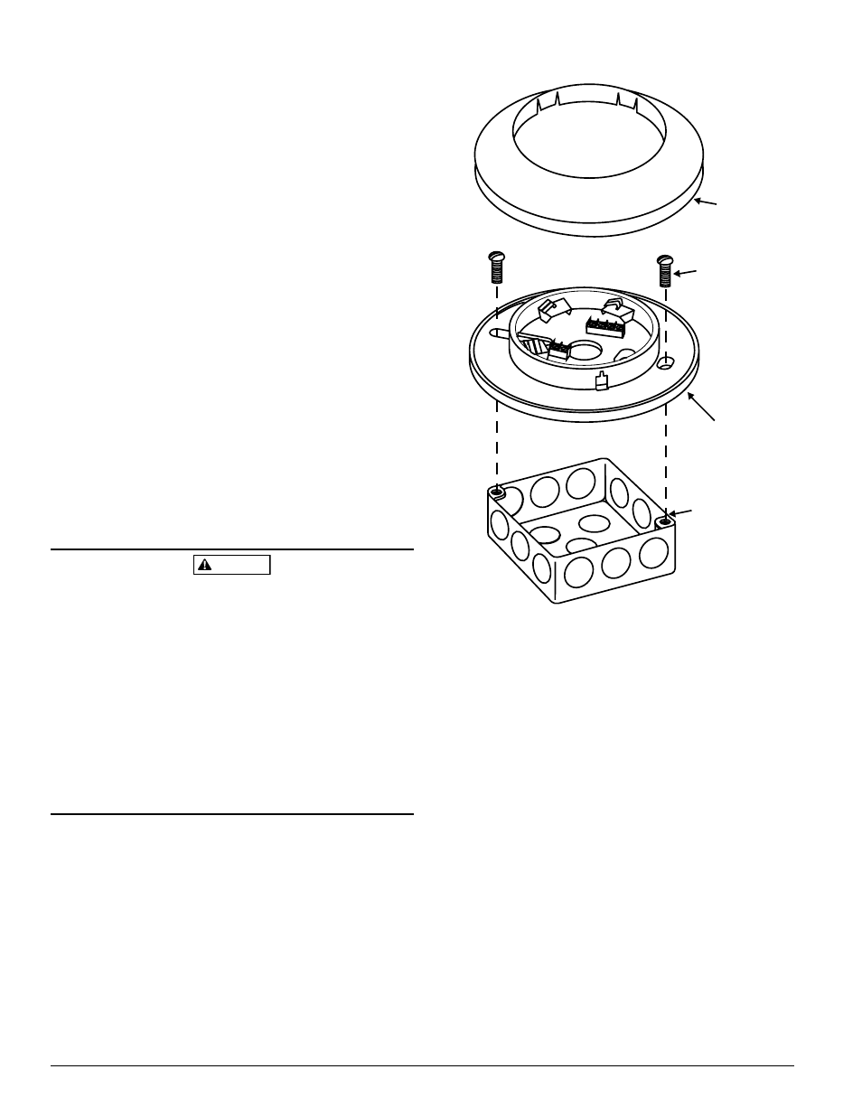
SCREWS (NOT
SUPPLIED)
BOX (NOT
SUPPLIED)
DETECTOR
BASE
SNAP ON
DECORATIVE
RING
Figure 1. Mounting the base to an electrical box:
C0148-00
or soldering to ensure a reliable connection. If shielded cable
is not used, leave terminal 6 in the screwed-down position.
Check the zone wiring of all bases in the system before
installing detector heads. This includes checking the wir-
ing for continuity, correct polarity, ground fault testing, and
performing a dielectric test.
A label is affixed to the base for recording the zone, ad-
dress, and type of detector being installed at the base loca-
tion. This information is useful for setting the detector head
address and for verification of the sensor type required for
that location.
Once all detector bases have been wired and mounted, and
the loop wiring has been checked, the detector heads may
be installed in the bases.