Scientech S310 Vector User Manual
Page 34
34
where:
V = voltage applied to the heater coil
R
c
= substitution heater resistance from step B
C = Cal coefficient 360401 = 1.018
360801 = 1.000
380401
=
0.974 380801
=
1.008
380402
=
1.024 380802
=
1.008
384UV5
=
1.021
388UV5
=
1.002
W = desired laser power in watts
D. Connect the DVM to the calorimeter’s DIN connector.
E. Apply the calculated voltage (V) to the electrical substitution heater.
F. Record the voltage reading of the DVM (V
c
).
G. Calculate the calorimeter’s output sensitivity (S) as follows:
S = V
c
/W
where:
S = calorimeter’s output sensitivity
V
c
= voltage output from the calorimeter in mV
W = desired laser power output.
The measured sensitivity should be ± 3 % of the calorimeters original sensitivity value.
D
ETECTOR
O
PERATION
W
ITHOUT AN
I
NDICATOR
:
Pyroelectric Detectors:
Standard and SP Models:
Standard and SP model pyroelectric detectors can be operated with a 1MΩ input oscilloscope. The peak
voltage shown on the oscilloscope can be divided by the V/J output sensitivity of the detector to calculate
energy.
HR Models:
HR pyroelectric detectors can be operated with a 50Ω input oscilloscope. The peak voltage shown on the
oscilloscope can be divided by the V/mJ output sensitivity of the detector to calculate energy.
Astral
TM
and Large Aperture Calorimeters:
Cable Requirements:
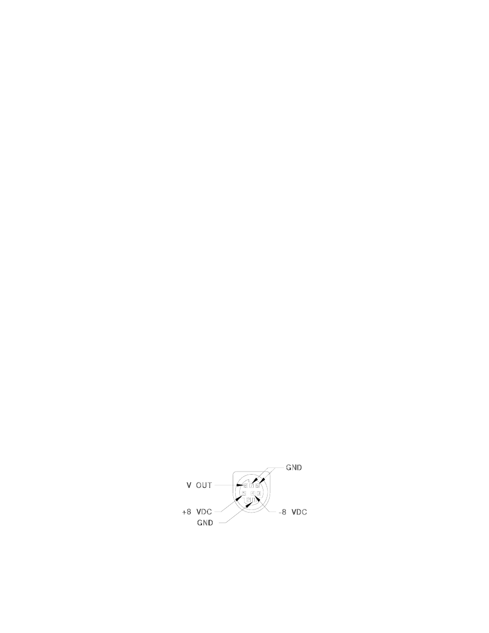
Astral calorimeters are powered up by the indicators. To use an Astral calorimeter without a Scientech
indicator, but with a volt meter or chart recorder, you must apply +/-8VDC to the mini DIN connector as shown
in Figure 7. The voltage output of the calorimeter, from pin 8, should be connected to the positive side of the
DVM or chart recorder. All 3 of the grounds should be tied together at the negative side. Pins 2 and 3 are not
used.
Figure 7
When large aperture calorimeters are used without an indicator their interface module is not used. The output
of the calorimeter is connected directly to the DVM or chart recorder. Large aperture calorimeters do not
require any power. The voltage output is on pin 1 of the DIN connector and should be connected to the positive
side of the DVM or chart recorder. Ground is on pin 3 and should be connected to the negative side. Pin 2 is
not used. Refer to Figure 6.