Ltra, Alorimeter, Pecifications – Scientech S310 Vector User Manual
Page 10: Npacking
10
U
LTRA
™
C
ALORIMETER
S
PECIFICATIONS
:
Model
UC150
UC150HD
UC150HD40
UC150UV
Type of Absorber
Surface
Surface
Surface
Volume
Maximum Beam Diameter
25mm
25mm
40mm x 40mm
25mm
Spectral Response
.25 - 35µm
.193 - 12µm
.193 - 12µm
.193 - .36µm
Maximum Average Power
Minimum Average Power
Noise Level
Maximum Power Density
200W/cm
2
1.5kW/cm
2
1.5kW/cm
2
50W/cm
2
@ 355nm
Maximum Peak Power Density
1MW/cm
2
100MW/cm
2
100MW/cm
2
101MW/cm
2
@ 355nm
Maximum Energy Density
Note 1
Note 2
Note 2
Note 3
Precision
Accuracy
Pesponse Time
Dimensions H x W x D - inches/cm
Weight - pounds/kgs
Indicator Compatibility
Note 1: UC150
Maximum J/cm
2
= 1000 x (pulse width)
1/2
to a maximum of 200J/cm
2
Note 2: UC150HD, UC150HD40
Maximum J/cm
2
= 4500 x (pulse width)
1/2
to a maximum of 14J/cm
2
Note 3: UC150UV
Repetitive pulses: 1.1J/cm
2
@ 355nm
Single pulses: 40J/cm
2
@ 355nm
150Watts
10Watts
0.1Watts
< 1 %
S310, S310D
± 5 %
40 seconds when connected to a Scienetch Indicator
4.9 x 3.4 x 4.0/12.5 x 8.6 x 10.2
2.7/1.2
U
NPACKING
:
The meter, detectors, and accessories are shipped in custom packing materials. All packing materials should be
saved for future damage free shipments.
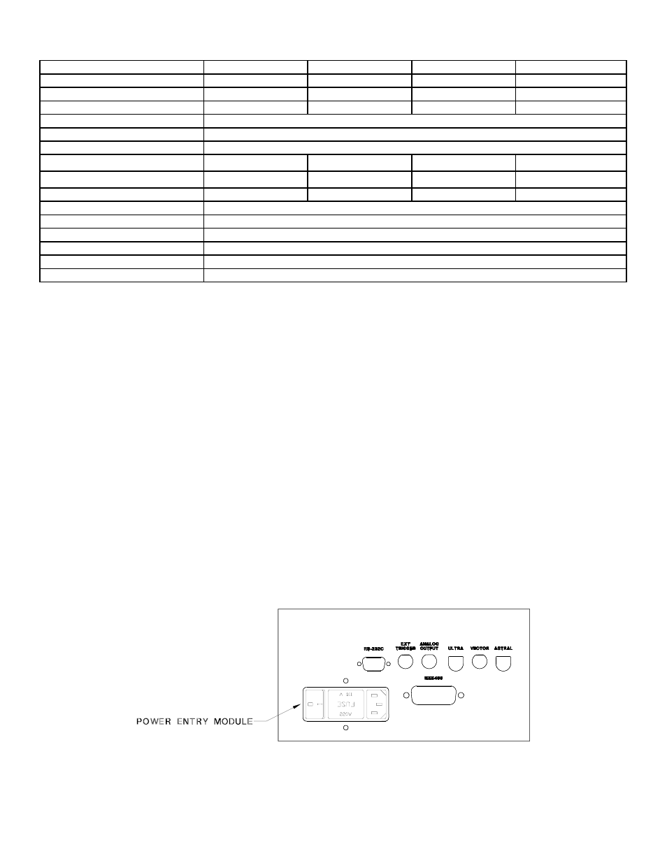
Before making any connections, verify that the power (VAC) requirement shown on the power entry module is
compatible with the actual AC power outlet to which the indicator will be connected. To change the indicator’s
voltage, proceed as follows:
1. Refer to Figure 2. Locate the power entry module and the fuseholder in the center of the module.
2. Remove the fuseholder by inserting a slotted screwdriver in the slot on the right side and prying it out.
3. Slide the voltage selector out, flip it over and re-insert it into the fuseholder.
4. Re-insert the fuseholder into the power entry module.
S310 Rear Panel – Figure 2