Installation instructions (cont'd), Figure 4b - vertical dual vent terminal, Install dual vent adapter box (cont'd) – Reznor VR Option - Installation - Dual Vent Kit User Manual
Page 4: 4 cap 6 cap concentric vent pipes
Form RZ-NA-I-VR/TRPA-DV, Page 4
3. Install Dual Vent Adapter
Box (cont'd)
12-1/8
(308mm)
6-1/2 (165mm)
1/2
(13mm)
6-1/2 (165mm)
5-1/2
(140mm)
2-1/4 (57mm)
1 (25mm)
2-1/4
(57mm)
4 Cap
6 Cap
Concentric
Vent Pipes
FIGURE 6 -
Attach Vent Caps
FIGURE 5 - Attach field-
supplied rigid bracing to
support angles only
Installation
Instructions
(cont'd)
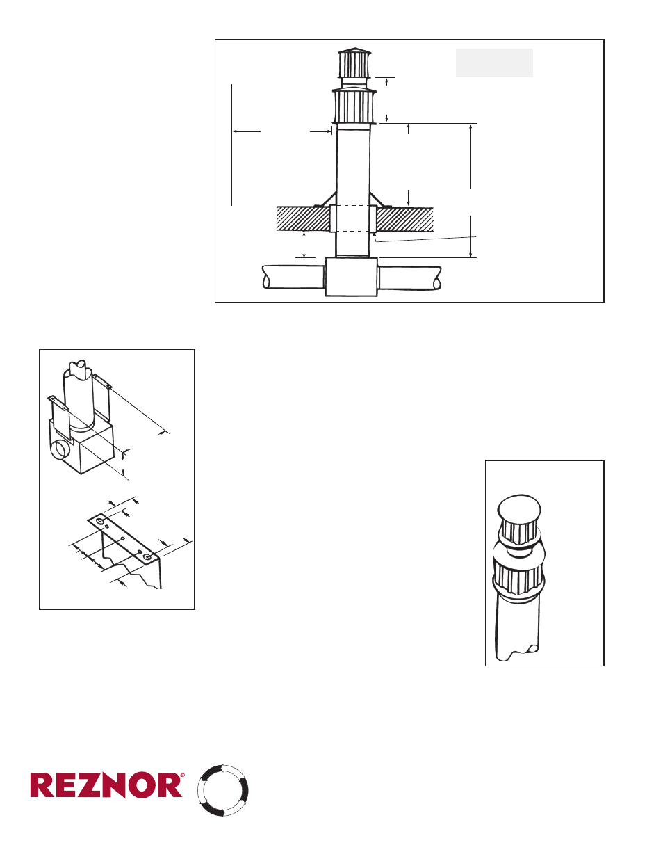
FIGURE 4B - Vertical Dual
Vent Terminal
6 ft (1.8M)
minimum
6 ft (1.8M)
maximum
Vertical extension must
be 6 (152mm) higher
than the anticipated
snow depth but no less
than 2 ft (.6M) above
the roof.
Dual Vent
Adapter
Box
Vent Pipe
from heater.
Vent Pipe
from heater.
6 (152mm) minimum
to combustible material
Approved clearance thimble
is required when flue pipe
extends through combustible
materials. Follow the require-
ments of the thimble and/or
vent pipe manufacturer.
NOTE: Drawing
is not proportional;
read all dimensions.
12 (305mm)
minimum
Parapet or
Adjoining Building
The dual vent adapter box must be attached securely to the building to adequately
support the weight of the adapter box plus the concentric pipes and the two vent
caps. Following dimension and clearance requirements in either FIGURE 4A or
4B
and in FIGURE 5, attach field-supplied rigid bracing or supports to the metal
support angles attached to the box in Step 1. Attach bracing or supports only at
the support angles provided. (If the support is attached elsewhere to the adapter
box, it may be impossible to remove the cover for later inspection of the inner
concentric pipe.)
If the roof or wall is constructed of combustible material, use an approved thimble.
If exiting through a roof, include a storm collar. All installations must be weather-
ized.
4. Attach Vent Caps (Refer to FIGURE 6)
First, attach the 6" vent cap. Slide the vent cap over
the end of the 4" pipe with the pipe extending through
the cap. Secure the vent cap to the 6" pipe with at
least three non-corrosive, evenly spaced screws.
Second, attach the 4" vent cap and secure in the same
way.
Using the tube of silicone rubber included in the option
kit, seal the gap between the 4" vent pipe and top of
the 6" vent cap.
5.
Installation of the dual vent option is complete.
Attach the 4" diameter vent runs from the heaters to
the inlet collars on the dual vent adapter box. Secure
with at least three evenly spaced, non-corrosive
screws and seal the joints with sealant or aluminum tape suitable for 550°F
Support the vent runs; do not rely on the dual vent adapter box for their support.
Follow the instructions in the heater installation manual to complete the installa-
tion.
Concentric vent pipes, 4" inner
and 6" outer, are both single-wall
vent pipe.
(800) 695-1901, www.RezSpec.com
©2006 Thomas & Betts Corporation, All rights reserved.
MANUFACTURER OF HEATING, COOLING, AND VENTILATING SYSTEMS
Trademark Note:
Reznor
®
is a trademark of Thomas & Betts.
6/06 OG POD Form RZ-NA
I-VR/TRPA-DV
CQS
CO
NVERGENT
QU
ALITY SYSTE
M
PR
ODUCT
AG
EN
CY
C
U
ST
O
M
ER
ST
A
R
T-
U
P
WARR
AN
TY
PROCE
SS
©2014 Reznor, LLC. Allr Rights Reserved
Trademark Note: Reznor is registered in at least the United States
0514 POD Form I-VR/TRPA-DV (Version 0.1)