Installation instructions – Reznor VR Option - Installation - Dual Vent Kit User Manual
Page 2
Form RZ-NA-I-VR/TRPA-DV, Page 2
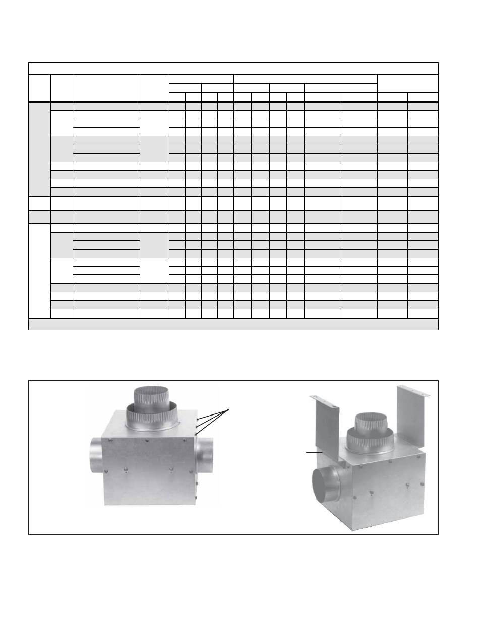
2. Attach Concentric Vent Pipes to Dual Vent Adapter Box
Attach the 4"-diameter vent terminal pipe to the inner concentric 4" collar on the
adapter box. See FIGURE 3. Secure with three non-corrosive screws spaced
evenly around the pipe. Seal joint with aluminum tape suitable for 550°F (Option
FA1, P/N 98266, or equivalent).
Installation
Instructions
FIGURE 2 - Attach
support angles to inlet
sides of dual vent
adapter box
1) Remove
three screws.
2) Use those
screws to attach
the support angle.
Repeat on the
other side.
Box before support angles
are attached
Box with two support
angles attached
1. Attach Dual Vent Adapter Box Support Angles
On one of the inlet sides of the adapter box, remove the three factory-installed
screws. Use these screws to attach the support angle. See FIGURE 2.
Repeat, attaching the second support angle to the opposite side of the box.
Vent Length Table - Applies to
INFRA-REZ Model Heater
with Dual Vent Option CC5
Calculate each vent length separately, including the equivalent length for the dual
vent adapter box and the length of the concentric pipe from the box to the vent cap,
in the total vent length for each heater. Do not exceed the maximum vent length.
Equivalent Length for
Max Min Max Min
ft
M
ft
M
ft
M
ft
M
50
20, 25, 30, 35, 40
4
20
5
6.1
1.5
3
0.9
1.5
0.5
3
0.9
6
1.8
20, 25
45
5
13.7 1.5
6
1.8
3
0.9
6
1.8
6
1.8
75
30, 35
35
5
10.7 1.5
5
1.5
2.5
0.8
5
1.5
6
1.8
40
20
5
6.1
1.5
3
0.9
1.5
0.5
3
0.9
6
1.8
30, 35
45
5
13.7 1.5
6
1.8
3
0.9
6
1.8
6
1.8
100 40, 45
35
5
10.7 1.5
5
1.5
2.5
0.8
5
1.5
6
1.8
50
20
5
6.1
1.5
3
0.9
1.5
0.5
3
0.9
6
1.8
125 30, 35, 40, 45, 50, 55, 60
4
60
5
18.3 1.5
12
3.7
6
1.8
12
3.7
6
1.8
150 40, 45, 50, 55, 60
4
60
5
18.3 1.5
12
3.7
6
1.8
12
3.7
6
1.8
175 40, 45, 50, 55, 60, 65, 70
4
60
5
18.3 1.5
12
3.7
6
1.8
12
3.7
6
1.8
200 50, 55, 60, 65, 70
4
60
5
18.3 1.5
12
3.7
6
1.8
12
3.7
6
1.8
TRPA
30-60 N/A
4
40
5
12.2 1.5
6
1.8
3
0.9
6
1.8
6
1.8
TRP
30-100 N/A
4
40
5
12.2 1.5
6
1.8
3
0.9
6
1.8
6
1.8
50
20, 25, 30
4
20
5
6.1
1.5
3
0.9
1.5
0.5
3
0.9
6
1.8
20, 25
45
5
13.7 1.5
6
1.8
3
0.9
6
1.8
6
1.8
75
30, 35
35
5
10.7 1.5
5
1.5
2.5
0.8
5
1.5
6
1.8
40
20
5
6.1
1.5
3
0.9
1.5
0.5
3
0.9
6
1.8
30, 35
45
5
13.7 1.5
6
1.8
3
0.9
6
1.8
6
1.8
100 40, 45
35
5
10.7 1.5
5
1.5
2.5
0.8
5
1.5
6
1.8
50
20
5
6.1
1.5
3
0.9
1.5
0.5
3
0.9
6
1.8
125 40, 45, 50
4
60
5
18.3 1.5
12
3.7
6
1.8
12
3.7
6
1.8
150 50, 55, 60
4
60
5
18.3 1.5
12
3.7
6
1.8
12
3.7
6
1.8
175 50, 55, 60, 65, 70
4
60
5
18.3 1.5
12
3.7
6
1.8
12
3.7
6
1.8
200 50, 55, 60, 65, 70
4
60
5
18.3 1.5
12
3.7
6
1.8
12
3.7
6
1.8
*
Must be deducted from the total vent length of each heater.
M
odel
VR
4
4
TR /
TR-H
4
4
Vent
Diameter
(inches)
90° Elbow
Dual Vent Adapter Box
*
Total Vent Length
Vent Length Table for Model VR, TRPA, TRP, TR, or TR-H with Option CC5, Dual Vent
Feet
Meters
Maximum Length of
Concentric Pipes
45° Elbow
Input
S ize
(000)
S traight Tube Length
(ft)