Reznor B5SM Option - Installation - Smoke Detector - Light Commercial User Manual
Page 3
D200-94-00 3 I56-1222-03
Temporal Sounder
The SSK451 accessory provides the option of sounding a
continuous or temporal pattern. The SSK451 will default
to sound in a continuous pattern. For a temporal pattern,
wire a field-installed jumper between terminals 2 and 3 on
the SSK451.
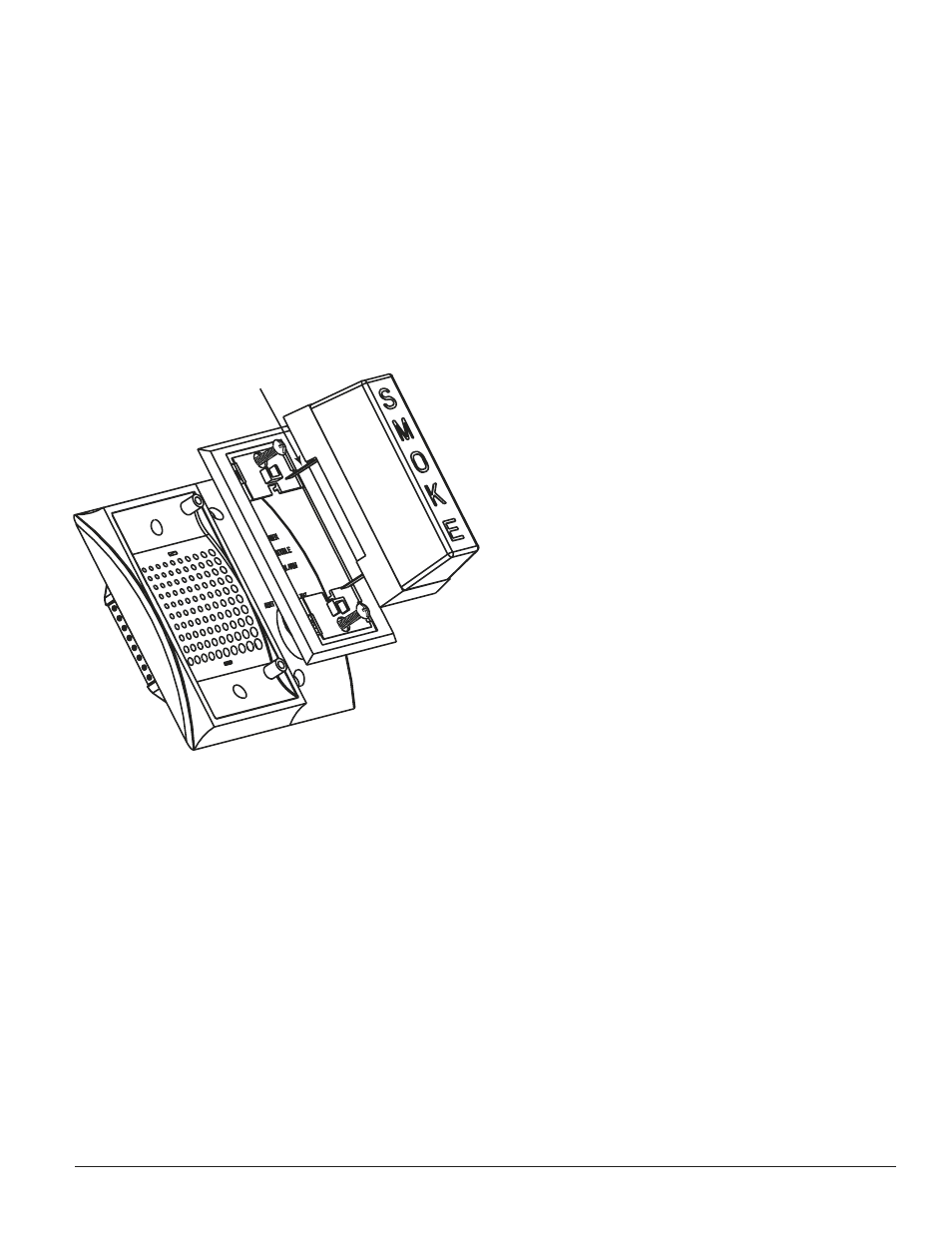
Mounting
Secure the SSK451 to a double-gang electrical box with the
four mounting screws provided.
Installation of the Optional Add-On PS24LO Strobe
This optional strobe can be purchased separately and is
easily added to the SSK451 accessory.
The PS24LO strobe will be mounted on top of the sounder,
on the left-hand side of the SSK451. Place one mounting
spacer between the SSK451 and the strobe adapter plate
at each screw attachment location. Attach the adapter
plate, spacer and SSK451 to the left-hand side of the dou-
ble-gang electrical outlet box with two mounting screws.
Slide the strobe terminals directly into the two slots in the
adapter plate and SSK451. The positive lug, which will be
colored red, must be installed into the top slot.
Grasp the catch area on the top of the strobe and squeeze
while applying inward force. Repeat for the catch area on
the bottom of the strobe.
Make sure the strobe catches fully engage into the slots in
the adapter plate and that no gap appears at the interface
between the strobe and adapter plate.
Optional SMOKE Strobe Lens
NOTE: To meet the code requirements of certain juris-
dictions, an optional SMOKE lens can be purchased sepa-
rately.
SMOKE lens, wall mount
PS12/24SLENSW
SMOKE lens, ceiling mount
PS12/24SLENSC
Please follow the instructions enclosed with the lens for
proper installation of the lens to the strobe.
Operation
The green “POWER” LED is illuminated whenever the duct
smoke detector is receiving power. With a DH100ACDC
duct smoke detector, the yellow “TROUBLE” LED is lit
when the sensor board is missing or the cover is removed
for more than twenty minutes. With a DH400 ACDC duct
smoke detector, the yellow “TROUBLE” LED is lit when the
detector head is missing. The red “ALARM” LED is dis-
played and the horn will sound whenever the duct smoke
detector is in alarm.
No LEDs will be illuminated if the duct smoke detector is
not receiving power.
Test Function
Insert the key and turn clockwise to the “TEST” position.
The red LED will illuminate and the horn will sound. If
an optional strobe is installed, it will pulse.
Alarm Indication
With the key in the “TEST” position, some time will
elapse (40 seconds maximum), depending on the duct
smoke detector type, before the red alarm LED will illumi-
nate and the horn will sound.
Reset Function
Turn the key counterclockwise to the “RESET” position
and hold. The red alarm LED should turn off and the
horn will cease sounding. Then, turn the key back to the
“ON” position and remove.
RED TERMINAL
ON TOP
H0485-00
- R6GD Option - Installation - Smoke Detector - Light Commercial R6GN Option - Installation - Smoke Detector - Light Commercial R8GD Option - Installation - Smoke Detector - Light Commercial Q6SD Option - Installation - Smoke Detector - Light Commercial R6GP Option - Installation - Smoke Detector - Light Commercial P6SP Option - Installation - Smoke Detector - Light Commercial P6SD Option - Installation - Smoke Detector - Light Commercial Q6SP Option - Installation - Smoke Detector - Light Commercial