Installation instruction – Reznor R6GF Option - Installation - Economizer - Light Commercial User Manual
Page 4
INSTALLATION
INSTRUCTION
DOWNFLOW ECONOMIZER # 558870
PACKAGE EQUIPMENT MODELS
*R6G(D,F) 024*–060* / *R8GD 036*-060*
*P6SD 024*-060* / *Q6SD 024*-060*
Step10a:
If installed make sure differential enthalpy wiring connections
are made in accordance with that kits instructions. Ensure that
wires are protected from all sharp edges, inadvertent grounding
and will not become entangled with filter or movable vanes.
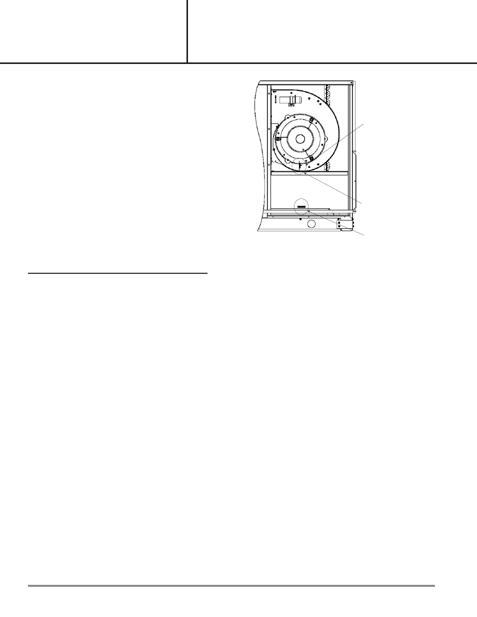
Step11:
Remove unit blower access panel and install mixed air sensor in
appropriate location (as shown in Figure) with two self tapping
screws and then make electrical connection. Replace blower
access panel.
Note: Some older units are equipped for mixed air sensor
location 1 installation for these units, if desired, the
mixed air sensor can be installed in location 2 for
optional performance. See Next Page for more
information.
Step 12:
Replace economizer top pan and install side panel and
appropriate upper close-off panel. Replace economizer filter
and filter access panel. Ensure all mounting screws, panels,
and doors are installed.
MIXED AIR SENSOR
LOCATION 1
SCREW TO SECURE
MIXED AIR SENSOR
LOCATION 2
3
Step 13:
Minimum Fresh Air Damper Position Adjustment
Damper minimum position keeps the outdoor air damper from closing completely during system operation for ventilation
of building contaminants and people occupancy. Consult your State or local codes as required.
1.
Ensure main power to outdoor unit is disconnected.
2.
Set thermostat “SYSTEM” switch to “OFF” position and “FAN” switch to “AUTO”.
3.
Install jumper wire across unit low voltage terminal board “R” and “G” terminal.
4.
Disconnect mixed air sensor from the W7459A terminals T and T1 and short terminals T and T1.
5.
Ensure the factory installed jumper is in place across W7459A terminals P and P1.
6.
Calculate the appropriate mixed air temperature per the following equation:
* (Return Air Temp. x % of Return Air) + (Outside Air Temp. x % of Outside Air) = Mixed Air Temperature
Example: Assume local code requires 10% outdoor air during occupied conditions, (200 CFM of total unit CFM = 2,000)
outdoor air is 50 Deg. F, and return air is 75 Deg. F.
Under these conditions, what is the mixed air temperature in the supply duct?
* (50 Deg. F x 0.1) + (75 Deg. F x 0.9) = 5.0 Deg. F + 67.5 Deg. F = 72.5 Deg. F
7.
Restore power to the outdoor section.
8.
Carefully adjust the MIN POS potentiometer on the W7459A control module (See Figure 3) with a small
screwdriver until the mixed air temperature reaches the calculated value. Ensure both sets of damper
blades operate properly.
9.
Once minimum position adjustments are completed, turn off power to the outdoor unit. Damper will move to
fully close.
10. Remove jumper wire across “R” and “G” on unit low voltage terminal board and T and T1 on the W7459A control
module.
11. Reconnect the mixed air sensor across W7459A terminals T and T1.
Step 14:
Dou ble check all elec trical con nec tions and make de sired enthalpy set tings.
See Page 7. C - Out door Enthalpy Change over Setpoint along with Fig ures 1 and 3.
Step 15:
Return power to the unit.