See unit wiring diagram for connections, Har ness ends at p1 – Reznor R6GF Option - Installation - Economizer - Light Commercial User Manual
Page 10
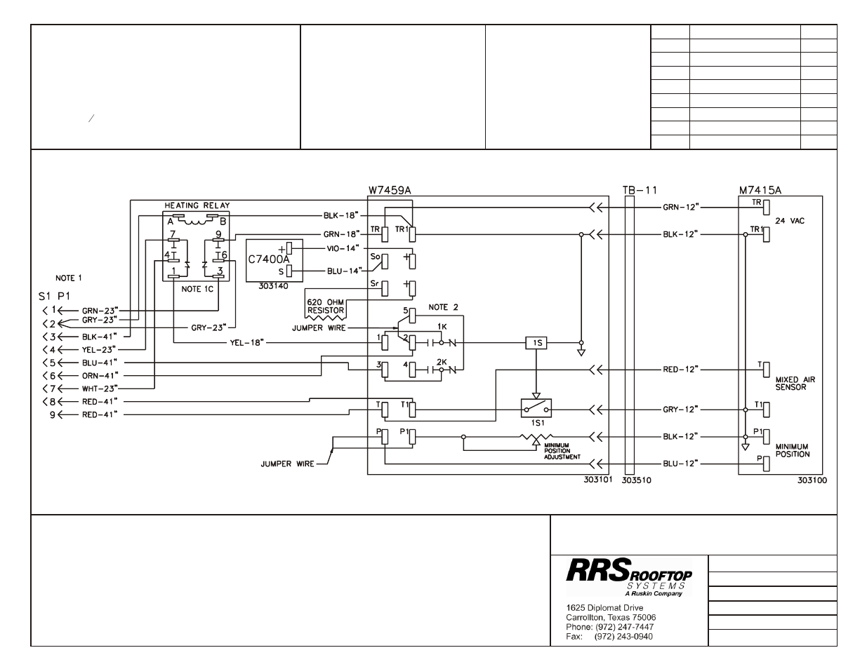
Modu lat ing Downflow Economizer
Notes:
1.
S1–Pin 2 connection is:
a.
connected to "Yellow" side of gas valve on package gas/electric units.
b.
connected to "W" low voltage terminal on package air conditioning units.
c.
connected to “O” thermostat terminal on package heat pump units.
See “Notes for Use with Heat Pumps”, Page 6, for required economizer wiring changes.
2.
For mechanical cooling (compressor) to energize during economizer cooling mode of operation, a thermostat
"Y2" call must be present. A 2 stage cooling thermostat is required for this application.
Date: March 14, 2012
Supercedes: 03-07-12
Drawn by: MGL
Unit #: 47-314-06D
Di a gram#: 4731406DW
Ap proved by:
WIRE COLOR CODE
BLK
Black
BLU
Blue
GRN
Green
GRY
Gray
ORN
Orange
RED
Red
VIO
Violet
WHT
White
YEL
Yellow
COMPONENT CODE
C7150C Mixed Air Sensor
C7400A Fresh Air Sensor
M7415A Damper Actuator 24v
P1
Economizer Plug
S1
Unit Plug
TB-11
Terminal Board
W7459A Logic Module
Re vi sion
Change
Date
A
Added notes to drawing
03-07-12
B
Changed Note 1
03-14-12
HARNESS DETAIL
CE# = WIRE END DESIGNATION
E2
STUD #6 18 Ga. Wire
E3
Female ¼ Quick Disc.
E4
Male ¼ Quick Disc. Insul
E6
Wire Nut Size 73B
E7
Raw End
E8
Female
3
16
Quick Disc.
HAR NESS
ENDS AT P1
See Unit Wiring Diagram for Connections