Reznor JT4BD Option - Installation - Indoor Fan Delay User Manual
Page 3
3
Electric Furnace:
1. Locate gray wire connecting blower relay
common terminal and transformer. Remove
wire from transformer.
2. Connect new gray wire to the fan relay
terminal #3 and the transformer terminal
where wire was removed in step 1 (piggy
back terminal).
3. Re-connect the gray wire removed in step 1
to the piggy back terminal at transformer.
4. Remove green wire from blower relay and
discard. Attach new green wire to terminal
#4 (terminal #5 on some models) on the fan
delay relay and route to “G”.
5. Attach new blue wire between terminal #1
on fan delay relay and terminal where the
green wire has been removed in the previous
step.
6. Locate the red wire connecting to the fuse at
the transformer. Cut the wire at a convenient
location and strip both ends at the cut. Strip
the new red wire at the piggy back terminal.
Twist all three wire ends together and secure
with a wire nut. Connect the straight terminal
of the red wire to terminal #2 on the fan delay
relay.
7. Complete installation as outlined in “General”
instructions on Page 1.
* Wires marked with an asterisk (*) are supplied
as part of the TDR kit.
† Labeled as terminal #5 on some models.
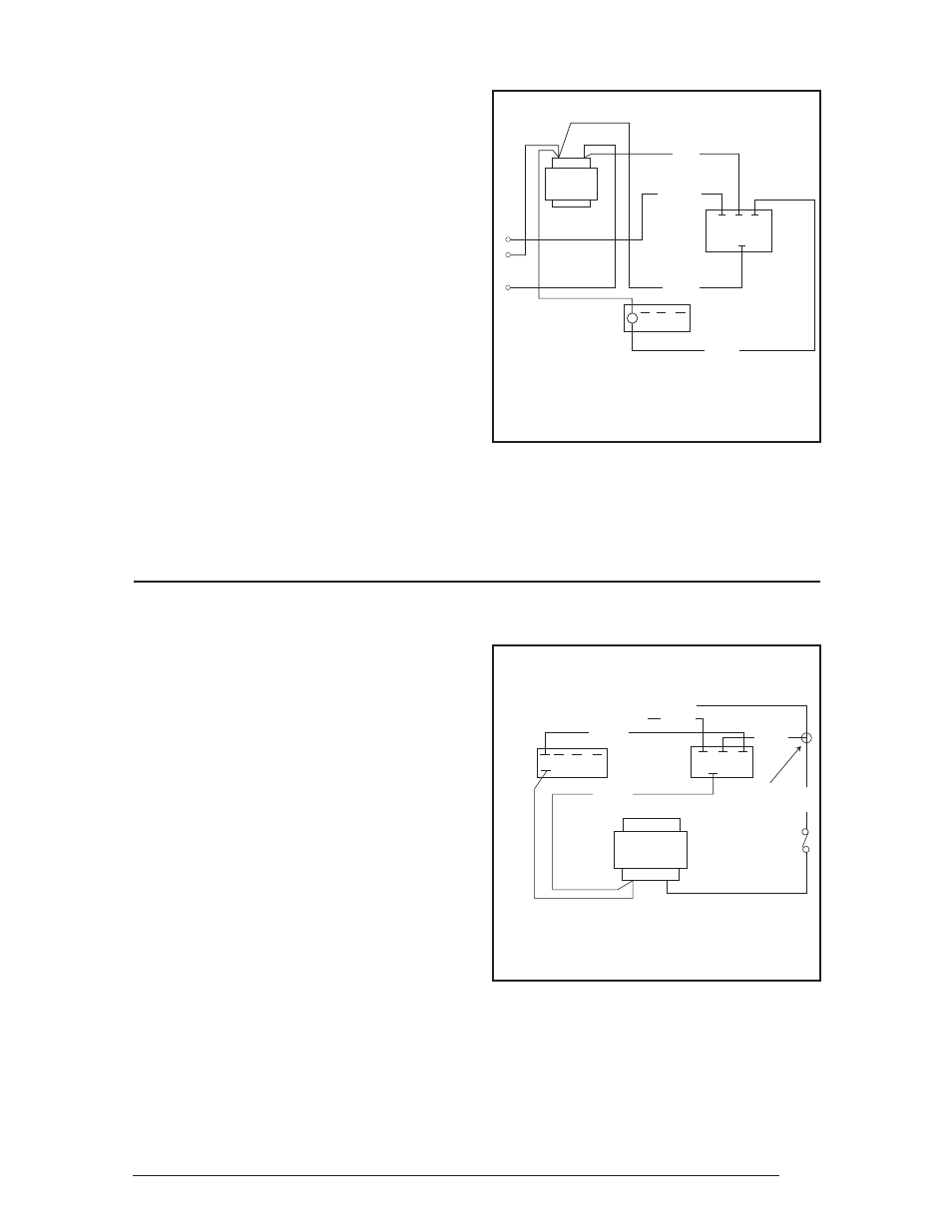
Figure 2. Wiring Diagram for
Air Handler Applications.
* Wires marked with an asterisk (*) are supplied as
part of the TDR kit.
† Labeled as terminal #5 on some models.
Figure 3. Wiring Diagram for E(1,2,3)EB
Electric Furnace Applications.
24V
TRANSFORMER
GRAY
RED
TIME
DELAY
RELAY
BLOWER
RELAY
1
2
3
4 †
G
C
R
GRAY
*
C NO NC
BLUE
*
GREEN
*
RED
*
24V
3
2
1
4†
Blower
Relay
Time
Delay
Relay
To Low Voltage
Thermostat Wires
splice/
secure
Grey
*
Transformer
C NO NC
Blue
*
Green
*
Red
*
To "G"
To "R"
Red
Fuse
Air Handler:
1. Locate gray wire connecting blower relay
common terminal and transformer. Remove
wire from transformer.
2. Connect new gray wire to the fan relay
terminal #3 and the transformer terminal
where wire was removed in step 1 (piggy
back terminal).
3. Re-connect the gray wire removed in step 1
to the piggy back terminal at transformer.
4. Remove green wire from blower relay and
discard. Attach new green wire to terminal
#4 (terminal #5 on some models) on the fan
delay relay and route to “G”.
5. Attach new blue wire between terminal #1
on fan delay relay and terminal where the
green wire has been removed in the previous
step.
6. Remove red wire from transformer terminal.
Attach new red wire between terminal #2 on
fan delay relay and transformer (piggy back
terminal). Re-connect the red wire removed
to the piggy back terminal.
7. Complete installation as outlined in “General”
instructions on Page 1.