Reznor RAD 350 Option - Installation - Vertical Louvers User Manual
Page 2
Form-I-OIL-VL, Page 2
Installation
Instructions (cont'd)
1. Assemble Vertical Louver Right Side Section
a) Position the Top/Bottom Members for the Right
Side (The square ends will be to the left and the
mitered ends to the right.)
• Position
top right member with mounting flange
up and dimples down.
• Position the
bottom right member with the
mounting
flange down and the dimples up.
b) Attach the Louvers to the Top and Bottom Members
• Using the sheetmetal screws, attach the vertical
louvers with their edges extending beyond the front
outer edge of the top and bottom members.
• Stops are designed so that the louvers will turn
right.
2. Assemble Vertical Louver Left Side Section
a) Position the Top/Bottom Members for the Left
Side (The square ends will be to the right and the
mitered ends to the left.)
• Position
top left member with mounting flange up
and
dimples down.
• Position the
bottom left member with the mounting
flange down and the dimples up.
b) Attach the Louvers to the Top and Bottom Members
• Using the sheet metal screws, attach the vertical
louvers with their edges extending beyond the front
outer edge of the top and bottom members.
• Stops are designed so that the louvers will turn
left.
3. If the heater is installed, turn off the power supply
before installing assembled vertical louver sections.
4. Install the Right Section -- Position the assembly
in front of the horizontal louvers so that the mitered
edges line up with the inside edge of the corner post
nearest to the burner. Using the mounting holes in the
top and bottom flanges as guides, attach the louver
assembly to the heater using the TEKS (self-drilling
screws).
5. Install the Left Section -- Position the assembly
in front of the horizontal louvers so that the mitered
edges line up with the inside edge of the corner post
nearest to the large outer access panel. Using the
mounting holes in the top and bottom flanges as
guides, attach the louver assembly to the heater
using the TEKS (self-drilling screws).
6. Adjust both the horizontal and vertical louvers to
provide the desired air pattern. If the heater is
installed, restore the power and check operation.
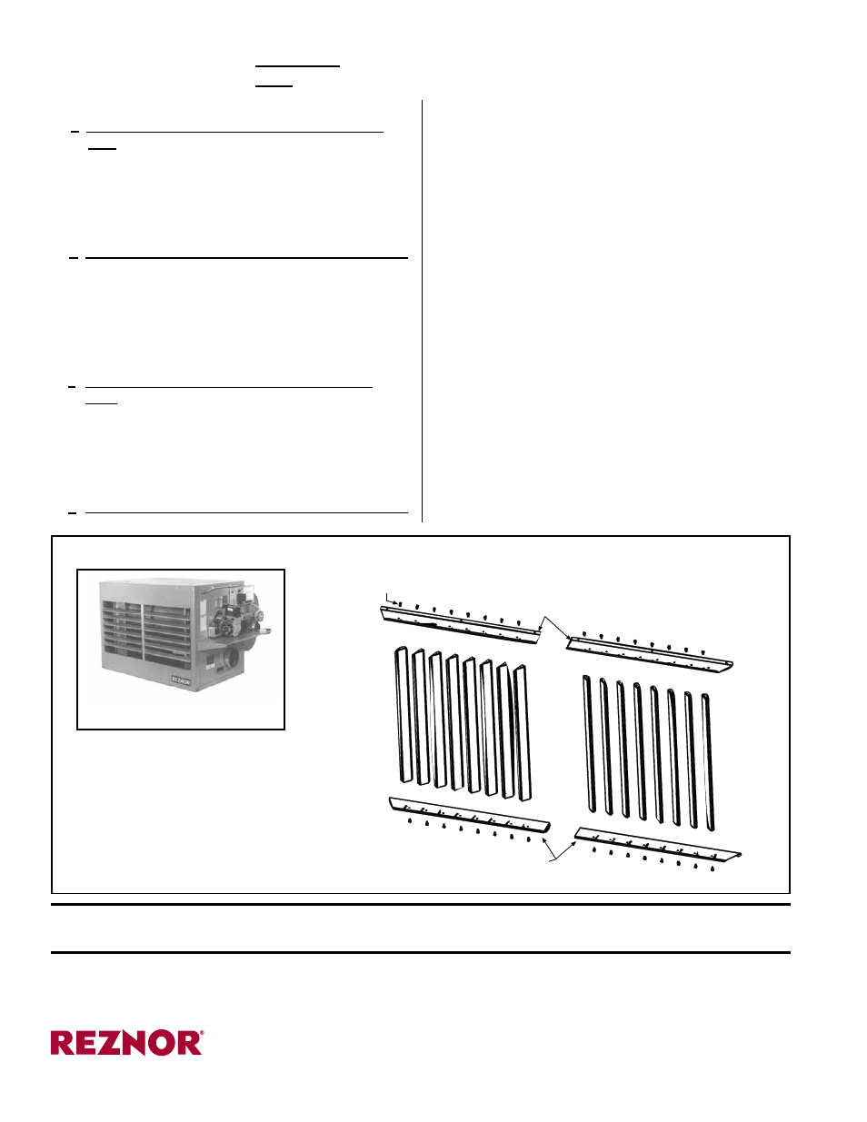
Model RA350
FIGURE 2 - Vertical Louvers for RA/RAD350
Assemble right and left vertical
louver sections
Position each section in the heater
discharge in front of the horizontal
louvers and attach
Adjust louvers for desired air
distribution. Do not adjust beyond
stops.
CAUTION: To avoid getting burned, adjust louvers while the heater is not in operation. If
louvers are adjusted while the heater is in operation, wear protective gloves.
Section B - Applies to Option Package for Model RA/RAD 350
only (See FIGURE 2.)
Left Side Section
Right Side Section
Bottom Members (position with
flanges down and dimples up)
Mitered
End
Vertical
Louvers
Sheetmetal screws
for attaching louvers
Top Members (position with
flanges up and dimples down)
Mitered
End
www.ReznorHeaters.com
(855) 854-3172
©2014 Reznor, LLC. All rights reserved.
Trademark Note: Reznor
®
is registered in at least the United States.
0514 (Serial No. Date Code BNE) Form I-OIL-VL (Version .2)