Reznor RAD 350 Option - Installation - Vertical Louvers User Manual
Installation form for option cd1, vertical louvers, Description/ application installation instructions
Form I-OIL-VL, PN 122408R1, Page 1
Installation Form for Option CD1,
Vertical Louvers
Applies to:
Model OH 95, 140, and 190
and Models RA/RAD 350
CAUTION: To avoid
getting burned,
adjust louvers
while the heater is
not in operation. If
louvers are adjusted
while the heater is
in operation, wear
protective gloves.
WARNING
Improper installation, adjustment, alteration, service, or maintenance can cause property
damage, injury or death. Read the installation, operation, and maintenance instructions
thoroughly before installing or servicing this equipment. Service should be done by a
qualified service person.
Description/
Application
Installation
Instructions
Section A - Applies to
Option Packages for
Model OH 95, 140, and
190 (See FIGURE 1)
1. Assemble vertical louvers to the top and bottom members using the sheetmetal
screws provided.
a) Vertical louver edges should extend beyond the front outer edge of the louver
top and bottom members.
b) Stops are designed so that the louvers on the right turn right and the louvers on
the left turn left.
2. If the heater is installed, turn off the power supply before installing the vertical lou-
vers. Attach the vertical louver assembly using the holes in the front heater panels
and the TEKS (self-drilling screws) in the option package. Adjust both the horizon-
tal and vertical louvers to provide the desired air direction.
3. If the heater is installed, restore power and check operation.
Form I-OIL-VL
Optional vertical louvers require field assembly and installation. The assembled lou-
vers fit in the air discharge over the factory-installed horizontal louvers. Vertical louvers
provide a more dispersed air distribution pattern.
Components of each package are listed in the table below. Before beginning installa-
tion, verify that the package is compatible with the heater model and size.
Model
OH95
OH140/190
RA/RAD350
Option Package
P/N 121858
P/N 121859
P/N 144963
Components:
Qty
P/N
Qty
P/N
Qty
P/N
Top and Bottom Members
2
119859
2
119860
--
Top Left/Bottom Right Members
--
--
2
144432
Top Right/Bottom Left Members
--
--
2
144433
Vertical Louvers
10
95937
14
95937
16
95938
Sheetmetal Screws, #10 x 1/2" lg
20
11813
28
11813
34
11813
Teks (self-drilling screws), #10-16 x 1/2" lg
4
37661
6
37661
14
37661
Installation should be done by a qualified agency in accordance with these instructions
and in compliance with all codes and requirements of authorities having jurisdiction.
Select the Section that applies to the model and size of heater being serviced.
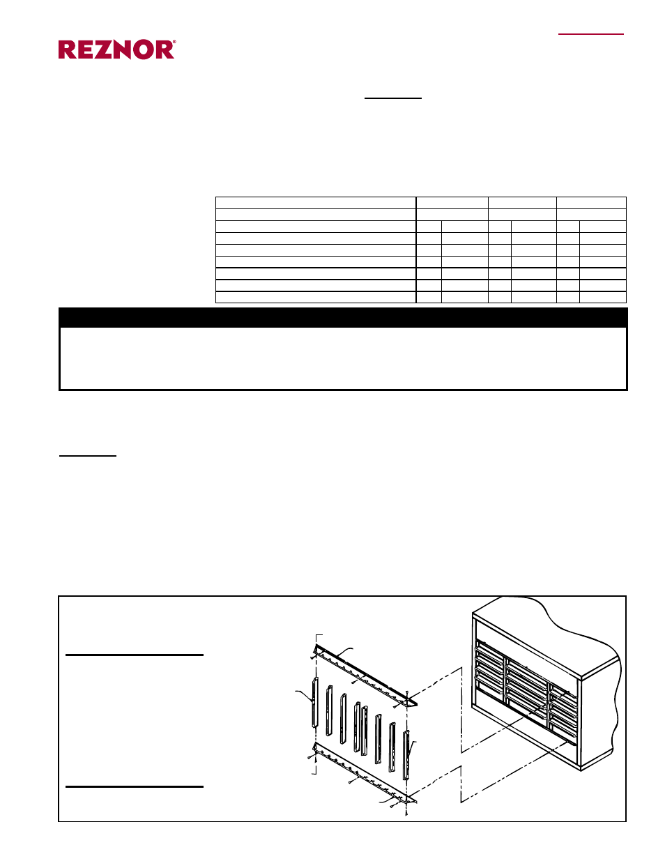
Sheetmetal Screw
Top Member
Vertical
Louver
Left Side
(NOTE: All louvers
are not shown.)
TEK (self-drilling
screw)
Vertical
Louver
Right
Side
Bottom Member
Sheetmetal
Screw
TEK (self-drilling
screw)
FIGURE 1 - Vertical Louver
Assembly and Installation on
Model OH/95/140/190
(See Section B, page 2, for Model RA/RAD 350)