Applies to – Reznor LDAP Option - Installation - Discharge Air Nozzles Installation User Manual
Page 3
Form RZ-NA I-LDAP-N, P/N 208899 Rev 3, page 3
Option CD57 or CD58 - Repeat nozzle installation as required for each heat section. If the heater is installed, turn
on the electric and the gas. Light the heater following the lighting instructions. Check for proper operation.
Option CD59 - Continue to SECTION B.
FIGURE 5 - Installing
Louvers in Nozzle Outlet
Airflow direction;
springs are on
the upper end.
Airflow direction;
springs are on
the lower end.
Airflow direction depends on how the louvers are installed.
SECTION B
1. Option CD59 - Assemble the Frame for 4-Way Louvers (See FIGURE 6.)
Using the 3/8” long screws in the kit, attach both sides to the supports.
Applies to
n Option CD59
Using the 1/2” self-drilling
screws in the kit, reach
inside the nozzle and
attach the nozzle top and
bottom to the heater outlet.
Use the holes in the nozzle
top and bottom to position
the screws.
Louver Frame
Side (P/N 207936)
(sides are identical)
Top Louver Frame
Support (P/N 207937)
(note height of support)
Assemble louver frame with
screws provided (P/N 195638).
Bottom Louver Frame
Support (P/N 208637)
(note height of support )
2-3/32 (53mm)
2-31/32 (75mm)
FIGURE 6 - Assemble the Louver Frame
5. Install the Louvers in the Nozzle Outlet
All Options - Before actually installing the louvers, note the louver curve and determine how the louvers
should be positioned to provide the optimal throw pattern. Louvers may be installed with the curve all the
same direction (either way) or the right half one way and left the other as illustrated in
FIGURE 5. Follow
the instructions and refer to the illustration to install the louvers using the compression springs.
Louver Installation Instructions:
a) With the wider section of the louver facing out of the heater, place one of the compression springs over
the tab on the notched end of a louver. The end of the louver with the spring will fit in any direction in
the square opening. How the louver turns depends on which end of the louver is inserted first.
b) Depending on the airflow pattern selected, push the louver tab with the spring into a hole in the discharge
opening and insert the louver tab on the other end into the corresponding hole on the opposite side.
c) Continue installing until all louvers are in place. Adjust the louvers to provide the desired air throw
pattern.
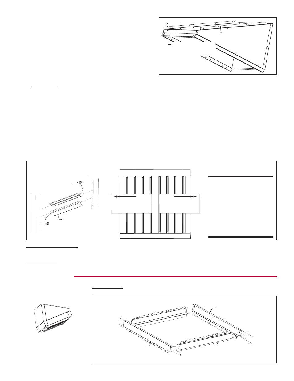
(1) Attach nozzle sides
inside heater outlet
with 3/8 screws.
(2) Attach nozzle top
and bottom with 1/2
self-drilling screws.
FIGURE 4 - Fasten
Assembled Nozzle
to Heater Outlet
(NOTE: Option
CD57 is illustrated.
Procedure is the
same for all
options.)
CAUTION: To avoid
getting burned, adjust
louvers while heater is
not in operation. If
louvers are adjusted
while heater is in
operation, wear
protective gloves.
Wider side of the
louver blade must
always be facing
out of the heater.
Compression Spring