Installation instructions, Applies to – Reznor LDAP Option - Installation - Discharge Air Nozzles Installation User Manual
Page 2
Form RZ-NA I-LDAP-N, P/N 208899 Rev 2, page 2
Installation
Instructions
WARNING: Improper installation, adjustment, alteration, service, or
maintenance can cause property damage, injury or death. Read the
installation, operation, and maintenance instructions thoroughly before
installing or servicing this equipment.
Installation should be done by a qualified agency in accordance with the instructions on this sheet and in compli-
ance with all codes and requirements of authorities having jurisdiction.
n
Option CD57 or CD58 ......Follow instructions in SECTION A.
n
Option CD59 .......................Follow instructions in both SECTIONS A and B.
All installations will also include the louvers that were shipped with the heater. Repeat the instructions to install a
nozzle on each heat section.
SECTION A
1. If the heater is installed, turn off the gas and the electric power.
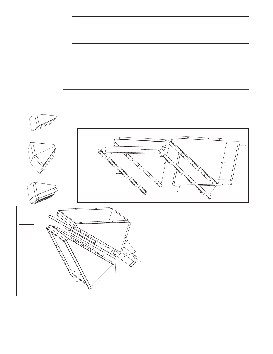
2. Assemble Nozzle
All Options - See FIGURE 2. Assemble a nozzle section. Use the 3/8” screws in
the kit to attach both sides to the top. Attach the bottom to both sides.
Options CD57 and CD58 - Use 3/8” screws to attach side fillers as shown.
Option CD59 - Do not attach side fillers; save to install later.
Option CD58 - Assemble the
second nozzle section
with-
out attaching the side fillers.
Attach the two nozzles and
the side fillers as shown to
create one nozzle with two
sections (See
FIGURE 3).
Position the nozzle bottom
filler over the seam between
the two bottom nozzle sec-
tions. Remove the screws that
line up with the holes in the
nozzle bottom filler. Re-insert
the screws securing the filler
over the seam.
Applies to
n Option CD57
n Option CD58
n Option CD59
3. If the louvers shipped with the heater have been installed in the heater discharge opening, remove them.
Save the louvers and the springs to be re-installed in the nozzle discharge.
4. Install the Assembled Nozzle in the Heater Outlet (FIGURE 4)
All Options - The discharge opening is square so the nozzle can be installed in any direction. Determine the
appropriate direction and position the assembled nozzle in the heater outlet so that the holes on each side are
lined up with the holes in the heater. Use the 3/8” screws in the kit to attach the nozzle sides to the heater.
Screw ends should be inside the nozzle.
Use 3/8 screws
(P/N 195638) from the option
package to assemble top, sides,
and bottom. If installing CD57
or CD58, attach side fillers.
Nozzle
Side Filler
Nozzle
Side Filler
Nozzle
Right
Side
Nozzle
Left
Side
Nozzle
Bottom
Nozzle Top
FIGURE 2 - Assemble a Nozzle Section
CD58 - Second
Nozzle Section
Assembly
CD58 - Nozzle
Section Assembled
in FIGURE 2.
Nozzle side
fillers attached
in FIGURE 2.
Nozzle Side Fillers - Install these two
side fillers when joining the two
sections of an Option CD58 nozzle.
Attach the two
assembled nozzles
and the side fillers
with the 3/8 screws
(P/N 195638).
Nozzle Bottom Filler -
After nozzle sections
are assembled, remove
appropriate screws and
reuse to attach nozzle
filler as illustrated.
FIGURE 3 -
If installing
Option
CD58,
assemble
the second
nozzle and
attach the
two nozzle
sections.