Reznor B Option - Installation - Burner Air Shutters Installation User Manual
Page 3
Mfg P/N 98293 Rev 2, Page 3
b) Position the air shutter assembly against the front of the burn-
ers.
c) Position the spacers between the slotted holes in the air shut-
ter assembly and the holes in the burner rack assembly. The
holes in the air shutter assembly are slotted to enable the air
shutter assembly to fit tightly against the burner openings.
Insert the sheet metal screws through the spacers and tighten.
Be sure that the air shutter assembly fits tightly against the
burner rack. See the illustrations in FIGURE 7.
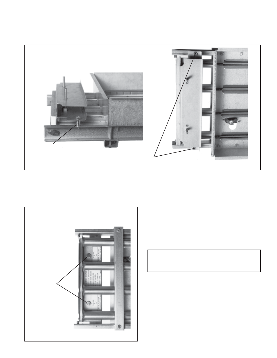
Screw and
Spacer
TOP VIEW
SIDE VIEW
FIGURE 7 - Installing the Air Shutter Assembly on the Burner Rack
Adjustment Screws
- Alternately turn
screws
counterclockwise
to open air shutters
WARNING: In the event of a pilot outage or
improper ignition, wait at least five minutes
before attempting to relight the heater.
6. Re-Assemble the Heater
a) Place the burner rack on its supports and lift it into position.
b) Replace/tighten the burner rack support.
c) Re-connect the pilot assembly.
d) Place the bottom panel on the hinge pins but do not close.
Be careful to re-assemble the heater correctly to ensure that no
unsafe conditions are created.
7. Start-Up and Air Shutter Adjustment
Turn on the electric and the gas. Light according to the instruc-
tions on the heater. Using a leak-detecting solution, check the
pilot connections for leaks. Tighten as needed.
Allow the heater to operate for about fifteen minutes before ad-
justing the air shutters. When the adjustment is made, close the
air shutters no more than is necessary to eliminate the problem
condition.
Observe the flame for yellow-tipping. A limited amount of yel-
low-tipping is permissible for propane (liquefied petroleum) gas.
Other fuels should not display any yellow-tipping.
Air Shutter Adjustment
Adjustment is made with the same adjustment screws that were
used to open the air shutters before the burner rack was returned
to the heater.
5. Open the Air Shutters
Turn the burner rack over so that the adjustment screws are
visible. (See FIGURE 8.) If the air shutters are not open, open the
shutters by alternately turning the adjustment screws counter-
clockwise.
Screws (with spacers) attaching the
air shutter to the burner rack
FIGURE 8 - Air Shutter Adjustment Screws