Reznor B Option - Installation - Burner Air Shutters Installation User Manual
Page 2
Form I-F/B-AS, Page 2
INSTALLATION INSTRUCTIONS (cont'd)
b) The bottom of the pilot assembly is now visible. Do the fol-
lowing:
1) Disconnect the pilot tubing from the pilot burner.
2) For standing pilot, disconnect the thermocouple from the
valve.
3) For spark pilot, disconnect the flame sensing wire and
high tension (spark) lead from the ignition controller.
c) Remove the Burner Rack
Heaters manufactured beginning 8/91 (Serial No. Date
Code AQH) - The burner rack support is indexed as illus-
trated in FIGURE 3. While supporting the burner rack, remove
the screws (two or three) that hold the burner rack support.
(For screw location, refer to FIGURE 4.) Remove the burner
rack support allowing the burner rack assembly to swing down
(See FIGURE 4).
Heaters manufactured prior to 8/91 (Serial No. Date Code
AQH) Loosen the sheet metal screws (two or three) located
at the front of the burner rack assembly. See FIGURE 3. These
screws retain the burner rack support. While supporting the
burner rack assembly, slide the burner rack support and re-
move it from the screws, allowing the burner rack assembly
to swing down (See FIGURE 4).
To Remove the Burner Rack -- With the burner rack assembly
"hanging" down, lift up on the rear and slide the assembly up
and out of the manifold support brackets.
FIGURE 4 -
Burner Rack
Hinged Down
for Removal
d) Allow the front of the burner rack assembly to drop down
lifting up on the rear and sliding the complete burner rack
assembly up and out of the manifold support brackets. The
burner rack assembly should now be completely removed
from the heater.
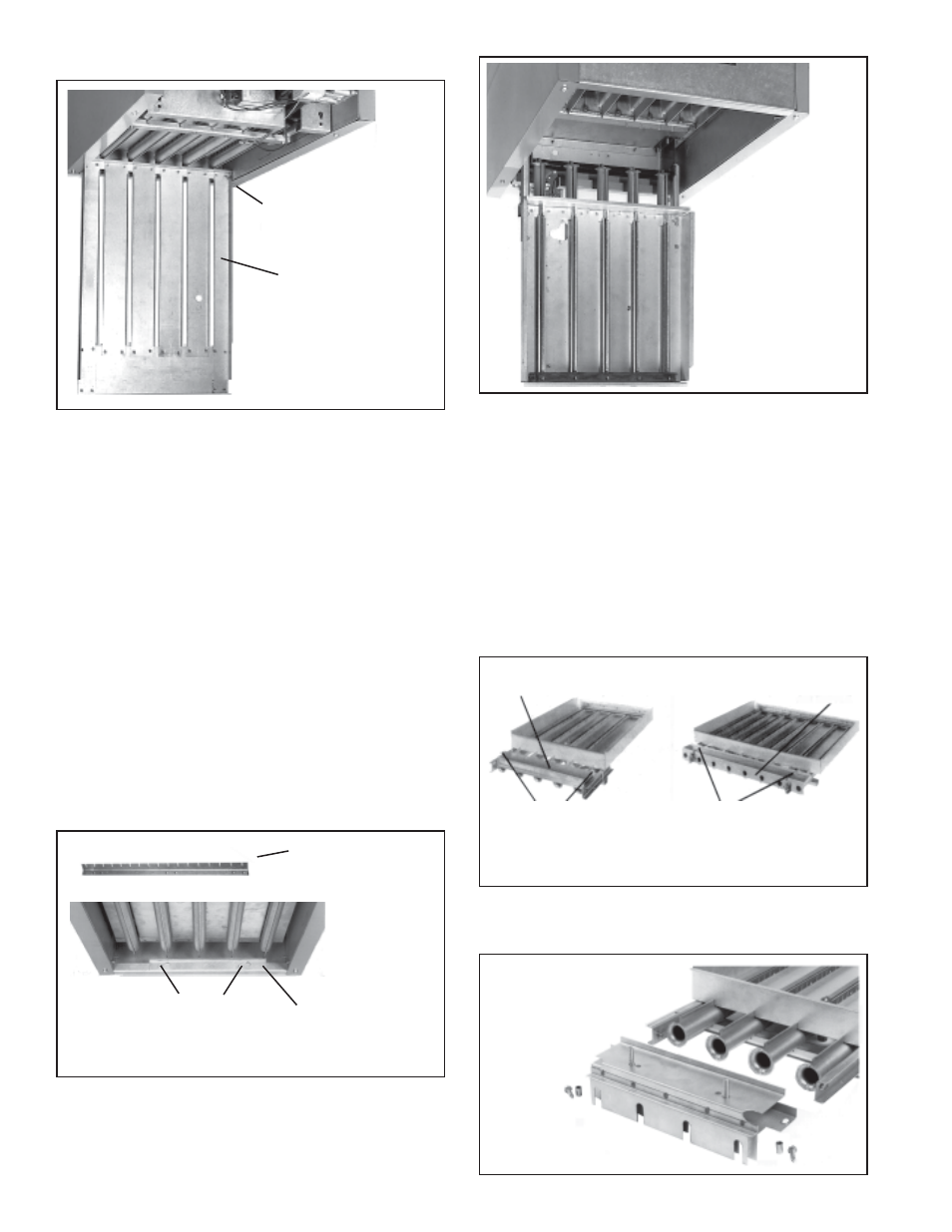
3. Remove Air Baffle (if applicable)
You may have to remove a factory-installed air baffle from the
burner rack. Visually inspect the burner rack to determine if it is
equipped with either of the air baffles illustrated in FIGURE 5.
Not all heaters are equipped with an air baffle. If your burner
rack is factory-equipped with an air baffle, remove and discard
the air baffle. FIGURE 5 indicates which screws to remove.
4. Install the Burner Air Shutters
a) Align the air shutter assembly with the front of the burners as
shown in FIGURE 6.
Air Baffle
Air
Baffle
Remove screws to
remove air baffle
Remove screws to
remove air baffle
FIGURE 5 - Burner Racks with Two Types of Factory-
Installed Air Baffles
FIGURE - 6
Align the Air
Shutter
Assembly
with the
Burner
Rack
FIGURE 3 - Burner Rack
Support and Retaining
Screws
Burner Rack Support
on units manufactured
prior to 8/91 was not
indexed
Screws
Burner Rack
Support with
Indexing
FIGURE 2 - Bottom Panel
Open for Access to the
Burner Rack
Hinge
Pin
Bottom
Panel