Installation instructions (cont'd) – Reznor B Option - Installation - Thermostat Bracket (Unit Mounted) Assembly (Option CM3) User Manual
Page 2
Form I-OPT-TB, P/N 98354 R5, Page 2
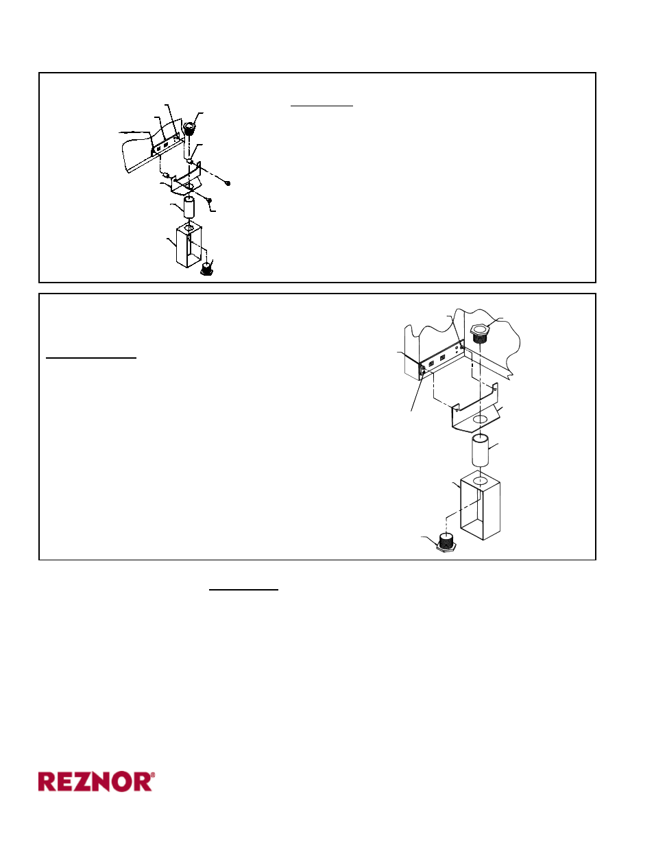
Remove and
save screw.
Chase
Nipple
Remove and
save screw.
Terminal Strip
1) Remove screws.
2) Slide assembled
bracket under.
3) Re-insert screws.
Electrical Box
Bracket
Coupling
Chase Nipple
Remove screw
and discard
Terminal Strip
Remove screw and discard
Chase Nipple
Spacer
Bracket
Coupling
Use 1 screws
in the kit.
Electrical Box
Chase Nipple
FIGURE 3 - Installing a Thermostat Bracket
on a Model F or B Unit Heater
2. Assemble and Attach Bracket (cont'd) - Select and follow illustrated
instructions for the applicable Model.
Installation
Instructions (cont'd)
FIGURE 2 - Installing a Thermostat Bracket on a Model VR Infrared Heaters
www.ReznorHVAC.com
(800) 695-1901
©2014 Reznor, LLC. All rights reserved.
Trademark Notes: Reznor
®
and T
CORE
2®
are registered in at least the United States.
All other trademarks are the property of their respective owners.
0514 Form I-OPT-TB (Version B.2)
MODELS F and B
NOTE: The screws and spacers in the kit will not
be used.
1) Assemble the Bracket - Connect the
electrical box to the mounting bracket using
the coupling and the nipples. (Use the parts
provided; do not increase the length of the
coupling.)
2) Attach the Assembled Bracket - Remove
the screws from the terminal strip on the
bottom left side of the back of the heater.
Slide the thermostat bracket under the
terminal strip. Re-insert the screws.
3. ALL MODELS - Mount the thermostat (not furnished with the kit) on the electrical
box. Wire the thermostat to the terminal strip. Be careful with thermostat leads.
Shorting thermostat wires to a metal surface will cause the transformer to fail,
requiring replacement.
Turn on the electric power and the gas. To operate, follow the lighting instructions
on the heater. Check for proper operation.
MODEL VR,
NOTE: Spacers are required for the access door to open.
1) Assemble the Bracket - Connect the electrical box to
the mounting bracket using the coupling and the nipples.
(Use the parts provided; do not increase the length of the
coupling.)
2) Attach the Assembled Bracket - Remove and discard
the screws holding the terminal strip on the end of the
burner/control box.
Use the screws and spacers in the kit to attach the
bracket. Follow the sequence in
FIGURE 2, from the
burner/control box --
first the terminal strip, second the
spacers, and
third the thermostat bracket.
- F Option - Installation - Thermostat Bracket (Unit Mounted) Assembly (Option CM3) UEAS Option - Installation - Thermostat Bracket (Unit Mounted) Assembly (Option CM3) UDBS Option - Installation - Thermostat Bracket (Unit Mounted) Assembly (Option CM3) UDBP Option - Installation - Thermostat Bracket (Unit Mounted) Assembly (Option CM3) UDAS Option - Installation - Thermostat Bracket (Unit Mounted) Assembly (Option CM3) UDAP Option - Installation - Thermostat Bracket (Unit Mounted) Assembly (Option CM3) VR Option - Installation - Thermostat Bracket (Unit Mounted) Assembly (Option CM3)