Installation instructions (cont’d), Figure 2 - unit pressure switch location – Reznor LDAP Conversion Info - High Altitude Kit Installation (Option DJ20) User Manual
Page 2
Form RZ-NA I-LDAP-HA, P/N 208081, page 2
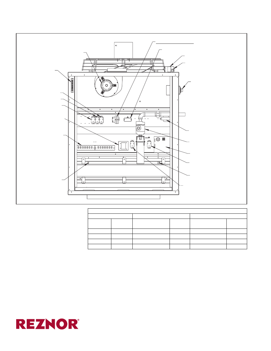
Fan
Motor
Unit Pressure Switch
Venter Motor Capacitor
Fan Motor Capacitor
High Limit Control
and Adjustable Destrat
Fan Control
Disconnect Switch
Transformer
Gas Valve
DSI Control (Circuit Board)
Fan Permissive Relay
Ignitor
Heat Permissive Relay
(Models 800 and 1200)
Flame Sensor
Terminal Boards
Limit Control
Vent Permissive Relay
(Models 800 and 1200)
Remote Destrat Relay
Destrat Relay
24V Thermostat
Terminal Board
Burner Assembly
Venter Motor
FIGURE 2 - Unit Pressure Switch Location
Installation Instructions (cont’d)
(800) 695-1901
www.RezSpec.com
©2014 Reznor, LLC. All rights reserved.
Printed in the U.S.A.
MANUFACTURER OF HEATING, COOLING, AND VENTILATING SYSTEMS
Trademark Note:
Reznor
®
is registered in at least the United States.
0514 Form RZ-NA I-LDAP-HA (Version 0.1)
Feet
Meters
Single Stage and
Two Stage High Fire
Two Stage
Low Fire
Single Stage and
Two Stage High Fire
Two Stage
Low Fire
6001-7000 1831-2135
2.6
1.5
7.4
4.2
7001-8000 2136-2440
2.5
1.4
7.1
4.0
8001-9000 2441-2745
2.4
1.3
6.7
3.8
9001-10000 2746-3045
2.4
1.3
6.7
3.6
Manifold Pressure Settings by Altitude above 6000 ft (1830M)
Altitude
Natural Gas (inches w.c.)
Propane Gas (inches w.c.)
IMPORTANT:
When the heater is installed, as part of startup, be certain to
adjust the outlet pressure of the valve(s) and to attach the high altitude
adjustment label
that is shipped with the heater. Adjustment instructions
and derated input rates and capacities are in the heater installation manual.