Hydraulic connection, Connection diagram: see page 10, Conexion hidraulica – Reznor WS Unit Installation Manual User Manual
Page 9: Esquema de alimentaciòn: en la página 10, Raccordement hydraulique, Schema d’alimentation: à page 10
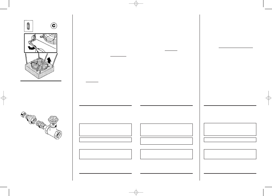
C - Suspended from the ceiling for vertical down
air flow as follows:
C1 - Determine the installation height,
C2 - Attach the suspension plates (provided) to be
unit heater with the four (4) M8 (metric) screws
with flat washers (also provided).
C3 - Hang unit by wire ropes, pull chains, bars, threaded
rod or similar means (follow all local codes regarding
hanging of ceiling suspended unit heater).
Determine the length of each rope/wire, etc and
attach to the ceiling. Use proper fastening methods
based on ceiling type and weight of unit.
See Technical Data Table. Tighten very well.
C4 - Raise the unit heater with and fasten it
securely to the suspensions plates.
C5 - The optional vertical louvers are
recommended for vertical air flow units
for 4 way air distribution.
D - By any other means or material considered
suitable by the installer or code.
E -
WARNING: Unit heater should not be
supported by the piping.
HYDRAULIC
CONNECTION
Connect the unit heater at the inlet and at the
outlet with a three-part joint union and a ball
valve; seal with pipe sealant.
DANGER: FLANGE SEALS MUST NOT BE MADE WITH
RUBBER OR OTHER MATERIAL THAT MELTS EASILY.
IN CASE OF OVERHEATED WATER OPERATION,
RUBBER SEALS MAY MELT.
MAXIMUM OPERATION PRESSURE 10 BAR 150 PSI
WARNING
MOUNT A THERMOSTATIC AIR VENT IF THE
DISTRIBUTION RING OF THE WATER OR STEAM IS IN
A LOWER POSITION THAN THE HEATER.
CONNECTION DIAGRAM:
see page 10
C - Para fijarlo a los anillos de suspensión al
techo (opcional), se necesita:
C1 - Decidir el lugar de la instalación.
C2 - Utilizar cable metálico, cadenas, tirantes,
barras o cualquier otro sistema de
anclaje del aparato en 4 puntos y fijarlo
al techo de manera estable.
C3 - Fijar las 4 placas de suspensión al
aparato con 4 tornillos M8 y arandelas
planas. Apretar y ajustar correctamente.
C4 - Levantar el aparato de manera adecuada
y fijarlo a las suspensiones.
C5 - Recomendamos la installación del
difusor opcional para dirigir el aire
en 4 direcciones.
D - Con cualquier otro método o material
que el instalador considere idoneo.
E - No fijar el aparato con los tubos de
instalacíon.
CONEXION
HIDRAULICA
Para évitar fugas, utilizar juntas de estanqueidad
adecuadas (teflón, cañamo o similar). Tanto en
impulsión como en retorno, conectar mediante
racord universal y válvula esférica.
EN CASO DE FUNCIONAMIENTO CON AGUA RECA-
LENTADA, ES OBLIGATORIO UTILIZAR BRIDAS (CON
JUNTAS RESISTENTES A ALTAS TEMPERATURAS) EN
LUGAR DE RACORD.
PRESIÓN MÁXIMA DE EJERCICIO: 10 BAR / 150 psi.
ATENCION
PONER UN PURGADOR DE AIRE EN CASO DE QUE EL
ANILLO DE DISTRIBUCIÓN DEL AGUA O DEL FLUIDO
ESTÉ EN UN NIVEL INFERIOR RESPECTO AL APARATO.
ESQUEMA DE ALIMENTACIÒN:
en la página 10
C - Pour le fixer avec des oreilles de
suspension au plafond il faut:
C1 - Décider la position de l’installation.
C2 - Se procurer des cordes métalliques,
petites chaînes verboquet, barres ou
autre chose capable de soutenir l’appareil
sur 4 points et le fixer au plafond de
façon stable.
C3 - Fixer les 4 oreilles de suspension
(optional) à l’appareil avec 4 vis M8 et
rondelles plates. Bien serrer.
C4 - Soulever l’appareil de façon appropriée
et le fixer très bien aux suspensions.
C5 - Conseillons l’installation du diffuser
optional pour diriger le flux de l’air dans 4
directions.
D - Avec n’importe quel autre moyen ou
matériel retenu approprié de la part de
l’installateur.
E - L’appareil ne doit pas êthre fixé par la
tuyauterie.
RACCORDEMENT
HYDRAULIQUE
Raccorder l’appareil soit en entrée qu’en
sortie avec un joint à 3 pièces et soupape à
bille avec chanvre et pâte de garniture.
SE RAPPELER EN CAS DE FONCTIONNEMENT AVEC
L’EAU SURCHAUFFEE QU’IL EST OBLIGATOIRE DE
MONTER LES BRIDES AVEC DES GARNITURES PAS
EN CAOUTCHOUC, A LA PLACE DU JOINT.
PRESSION MAXIMUM PENDANT LE FONCTIONNEMENT:
10 BAR / 150 psi
ATTENTION
METTRE UN EVENT D’AIR AU CAS OU L’ANNEAU
DE DISTRIBUTION DE L’EAU OU DU FLUIDE SOIT
INFERIEUR A LA POSITION DE L’APPAREIL.
SCHEMA D’ALIMENTATION:
à page 10
9/A
9
Manuale REZNOR 4050489 17-07-2007 11:21 Pagina 16