Appendix d top connector interconnect – PS Engineering PMA7000CD Installation Manual User Manual
Page 34
PS Engineering
PMA7000CD Audio Selector Panel and Intercom System
With PCD7100-R Remote Compact Disc Player
Installation and Operator’s Manual
200-790-0010
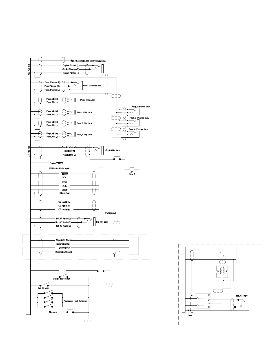
Appendix D
Revision 10, September 2005
Appendix D Top Connector Interconnect
19
10
20
21
Y
X
W
Z
1
4
D
16
15
T
1. Pin A is pulled low when
AUX is active.
2. All shields should be grounded
at audio panel only, other end
remains floating.
3. Interface to PCD7100-R,
11955, only.
4. All phone and mic jacks
must be floating from ground.
5. A pull type breaker IS REQUIRED
on PCD7100-R.
6. All wiring to conform to MIL 22750
or 27500, and be shielded as shown.
7. Passenger hook switches to be
located at positions where phone
access is desired.
Grounding of any switch causes all
passengers to be heard on the cellphone.
8. For music distribution information,
see Section 3.6.3.1.
9. For expansion unit, use part number
11606 or 11606R only.
10. When Pin J is grounded, the audio panel
is in Com 3 duplex mode.
This is used to interface with AirCell AT.01
AGT.01, or Guardian (or other duplex
telecommunications system.
11. When pin 18 is switched to ground,
the PA mode is activated, placing
pilot microphone on speaker output
when PTT active. See Sect 2.5.13.
12. This plan allows both source selection
AND volume control of the second input.
For passenger access volume control,
use a dual-ganged, audio taper,
Kit available from PS Engineering
under PN 250-790-0020.
12
11
N
5
E
6
F
7
H
Copilot PTT
Swap
Switch
L
V
M
Notes 2, 4
Note 7
Swap
PMA7000M-S Opt. CD J2 TOP CONNECTOR
Note 9
C
S
P
R
1
2 & 15
3
14
6
8
15
7
14
13
4
3
11
9
PCD7100-R
J1
14
13
R
1
11-33 VDC
Avionics Bus
Expansion Unit
p/n 11606
A
J
Note 1,
Note 10
18
________
PA Active
Note 11
Notes:
10K ohm
Audio Taper
Alternate Music Interconnect
( Note 12)
PCD7100-R
J1
4
3
11
13
R
14
16
15
T