Front of unit – PS Engineering PMA7000CD Installation Manual User Manual
Page 16
PS Engineering
PMA7000CD- Series Audio Selector Panel and Intercom System
Installation and Operator’s Manual
200-790-0010
Page 2-8
Revision 10, September 2005
2.5.18 Playback button Installation (J2, Pin 19- Options 1, ONLY)
To activate the Recording System playback, a momentary push button switch is required. This switch can
be located anywhere in cockpit convenient to the pilot's reach. The switch must be connected to pin 19 of
J2 of the PMA7000CD, and ground
2.6
Marker Beacon Installation
The marker beacon receiver is an option included in the PMA7000MS CD. Non-marker (PMA7000S) units
can provide audio interface with the external receiver (see section 2.5.4).
2.6.1
Marker Antenna Installation
A marker beacon antenna, appropriate to the type and speed of the aircraft, is required (not included). Re-
fer to aircraft and antenna manufacturer's installation instructions, as well as AC43.13-2A (or later revi-
sion), Chapter 3, for information on proper antenna installation techniques. The marker beacon antenna
must be mounted on the bottom of the aircraft.
2.6.2
External Marker Lights (7000MS-CD)
For installations that require external marker beacon lights, three outputs are available to drive 12-Volt
lamps only. The external output lamps are driven high (typically +9 VDC
±1.5 VDC unloaded, at MAX
brightness) when active. Maximum source current per lamp is 125 mA. Voltage varies with photocell dim-
ming.
2.6.3
Middle Marker Sense (7000MS-CD)
A Middle Marker Sense output signal is available from the 7000CD to flight control systems. This function
will not operate during the test mode. This output will go to +4.5 VDC (
± 1.0 VDC) when a valid Middle
Marker signal is received. This output is J1, pin 2.
2.6.4
Marker Audio Input (7000S-CD)
If using an external marker receiver, the audio input is J1, pin 21 (MKR input).
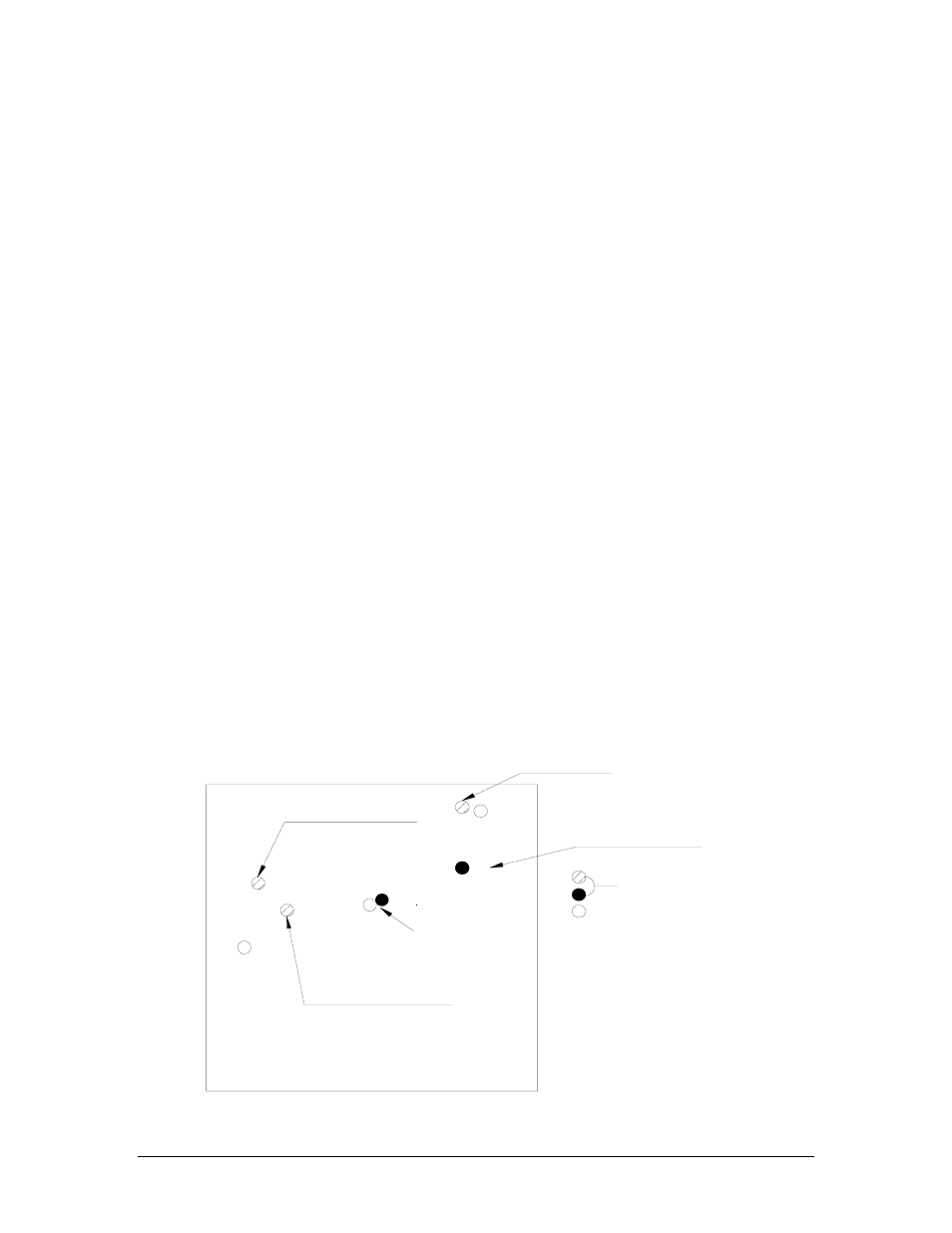
2.7 Adjustments
The PMA7000CD is factory adjusted to accommodate the typical requirements for most aircraft configura-
tions. There are five adjustments however, that will allow the installer to tailor the specific functions.
Marker Gain
CW- Reduce
Passenger Volume
CCW Increases
Marker Audio
CW Decrease Volume
MKR Low Sense
CW Decrease Sens.
Front of Unit
PMA7000M-S adjustment holes
Not used
Speaker Volume
CW-Increase
211
231
223
133
111
Figure 2-2- PMA7000CD Adjustments