PS Engineering PMA7000CD Installation Manual User Manual
Page 13
PS Engineering
PMA7000CD- Series Audio Selector Panel and Intercom System
Installation and Operator’s Manual
200-790-0010
Page 2-5
Revision 10, September 2005
2.5.6
Audio Panel interface
The PMA7000CD is designed to interface with standard aircraft avionics, and presents a 500
Ω receiver
impedance. For best results, a twisted-shielded cable is recommended from the avionics audio source to the
audio panel, with the shield grounded at the audio panel end.
Some avionics do not provide a separate audio low, and may introduce additional electrical noise into the
system. For best results, connect the audio low from the audio panel to the radio ground, using one conduc-
tor of the twisted-shielded cable.
2.5.6.1 Speaker
Load
The PMA7000-series contains a speaker amplifier. Some units with internal speaker amplifiers, such as
the King Radio KX170-series, require a resistive load to prevent damage if their speaker amplifier is not
used. Connect the speaker output from the unit to the load input on the PMA7000CD (J1, pins 19 and L, 16
and M. The speaker load in 16
Ω, 3W.
2.5.7
Com 3 Duplex (TEL) and Cell phone Function
As installed in the standard configuration, the PMA7000CD Com 3 function operates conventionally.
Pushing the Com 3 Xmt button places the receive audio from Com 3 in the headset and applies the pilot or
copilot microphone to the Com 3 when the appropriate PTT is activated.
The COM 3 input is designed to be used for a third aviation transceiver, but is capable of interfacing to a
cellular telephone, including AirCell. Note: Not all cells phone are compatible. PS Engineering, Inc is
does not guarantee function or operation of cell phone inputs or outputs.
The COM 3 duplex mode can be enabled when J2, Pin J is connected to aircraft ground (either directly or
through a switch). In this mode, the COM 3 input and output is compatible with many cellular telephones
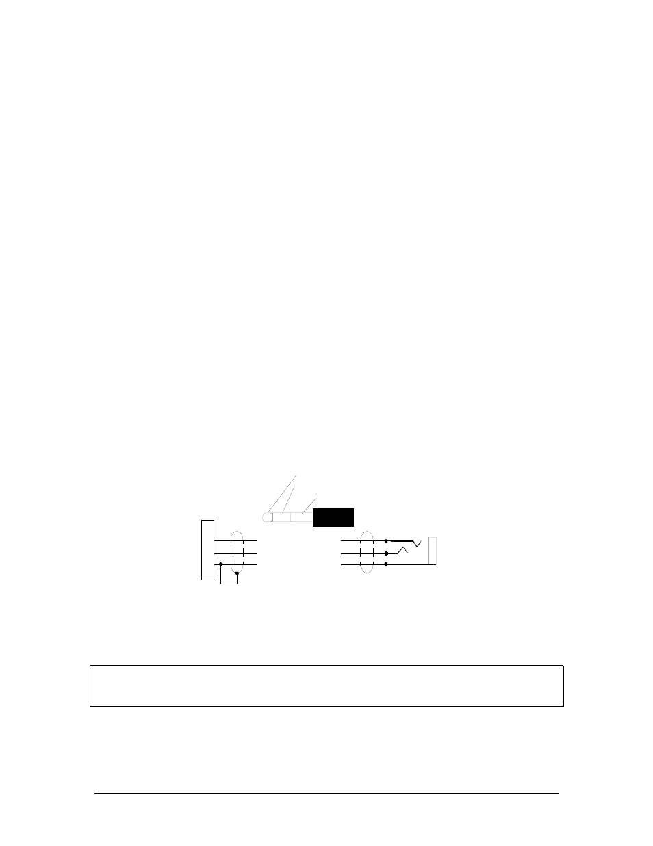
utilizing the hands-free headset interface. A 1/8" (using an adapter) or 3/32" jack can be installed on the
aircraft panel, which is interfaced with the PMA7000B as shown below. To connect the cellular telephone
to the jack wired in to COM 3, a patch cord is required. This patch cord is available from PS Engineering
under P/N 425-006-7026 (3/32" to 3/32"). A 1/8" to 3/32" adapter is available from Radio Shack P/N 274-
373.
3/32" Cellular Jack
COM 3 Mic Input
Com 3 Audio
Audio Lo
J
K
1
7000B
Bottom Connector
Cellular Plug (typical)
Tip= Microphone out
Ring= Speaker audio
Base=Ground
For Duplex (cell phone) operation
Pin J of top connector MUST BE GROUNDED
This is a typical interconnect
PS Engineering does not guarantee
compatability in all cases.
Cellular Phone
Interconnect
Unauthorized use of unapproved cellular telephone devices in aircraft is subject to FCC enforcement
action, which may include a $10,000 fine per incident. PS Engineering, Inc. does not endorse using
unapproved cellular telephone equipment in flight, and takes no responsibility for the user’s action.
2.5.8
Transmit Interlock
Some communications transceivers use a transmit-interlock system. To fully utilize the Split Mode feature,
this function must be disabled. Consult that manufacturer's installation manual.