Appendix c – j2 connector interconnect – PS Engineering PMA450 Installation Manual User Manual
Page 38
PS Engineering
PMA450 Audio Selector Panel and Intercom System
Installation and Operator’s Manual
200-450-0000
Appendix C
Rev. 3, November 2014
Appendix C – J2 Connector Interconnect
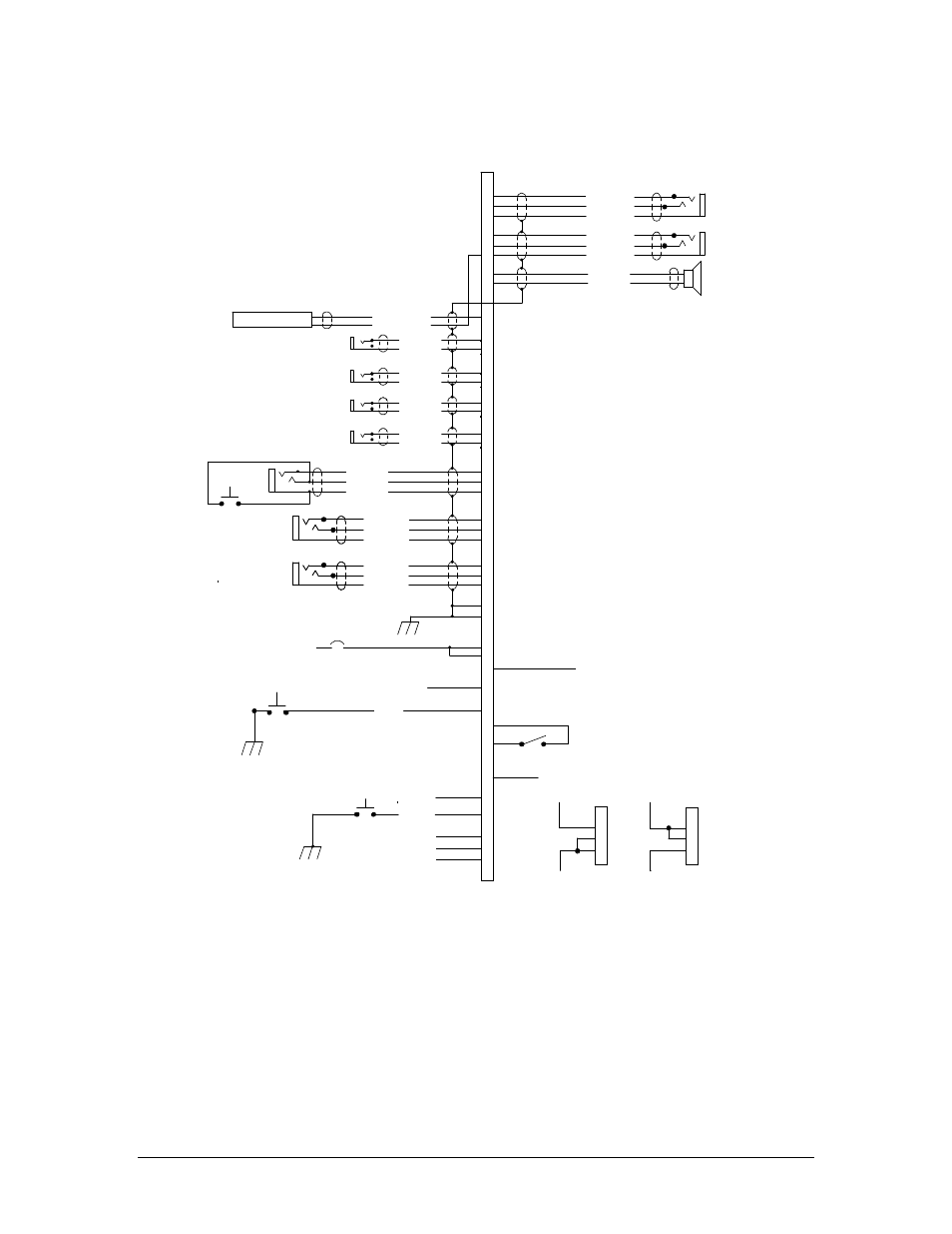
22
20
31
16
1
35
36
24
23
25
4
3
2
Copilot Phones (R)
Copilot Phones (L)
Copilot Phones Lo
Pass. 1 Mic Jack
Pass. Mic Lo
Pass. Mic Hi
37
38
Pass. 2 Mic Jack
Pass. Mic Lo
Pass. Mic Hi
39
40
Pass. 3 Mic Jack
Pass. Mic Lo
Pass. Mic Hi
41
42
Pass. 4 Mic Jack
Pass. Mic Lo
Pass. Mic Hi
32
33
34
Copilot Mic Audio
Copilot PTT
Copilot Mic Lo
Copilot PTT
Copilot Mic Jack
14
13
Ent. #2 Mute
12
Playback
PMA450 J2 CONNECTOR
(Sub-D 44-pin male on tray)
Ent. #2 Input
27
26
28
Ent. #2 Audio (R)
Ent. #2 Audio (L)
Ent. #2 Audio Lo
19
________
PA
Active
Note 8
Notes:
Ent. #1 Audio (R)
Ent. #1 Audio (L)
Ent. #1 Audio Lo
Ent. #1 Input
5
6
7
Copilot PhonesJack
Pilot Phones (R)
Pilot Phones (L)
Pilot Phones Lo
Pilot PhonesJack
14/28 Volt Lights Hi
14 V Lights Hi/28V Lights lo
Lights Lo
8
9
Ground Lug
Airframe Ground
11-33 VDC
See Note 4
PA Mute
18
29
30
Speaker Hi
Speaker Lo
44
43
Swap
Switch
Swap
10
11
Cockpit Speaker
1. All Power, and Ground wires must be #22 gage wire
Lighting #22 AWG, other wires minimum #24 AWG.
2. All shields should be grounded at audio panel only,
other end remains floating
3. Pins 8 and 9 connected through a 5 A breaker.
4. PA Mute trigger is a TTL level logic output that is pulled
low when PTT active for add-on Public Address systems.
5. All shielded wires must be MIL 22750 or 27500.
6. Optional switch to remotely activate playback
7. For music distribution information, see Sections 2.5.1 & 3.9
8. Pin 19 is switched to ground when the PA mode is activated,
placing pilot microphone on speaker output while pilot PTT active.
See Sect 2.4.10.2.
9. AUX enable goes low when SW#3 is selected.
Should NOT be used when audio source is installed and played
through SW3
10. S/N D 01150 and below ONLY:
Grounding Pin 30 places Marker Receiver into HI sensitivity
11. No connection to Pin 17, 29.
12. Use care when connecting music signal and ground inputs.
Refer to section 2.5.1 for more information.
Failure to properly interface music can result in
added noise.
13. Unswitched 4 audio low connected to copilot or
pilot phone low as convenient,
but should NOT go to music low
14. This switch toggles Music 2 mute on and off.
Unswitched Input #4 Hi
Unswitched Audio Lo
Unswitched Audio #4
15
See Note 9
7
6
5
28 V Lights Hi
28-Volt lights lo
7
6
5
14 V Lights Hi
14-Volt lights lo
AUX Enable
See Note 14
5A Breaker
See Note 3
Note 6
Note 12
Note 13
NO CONNECT
Note 10