Existing gma340 and pma8000 installations – PS Engineering PMA450 Installation Manual User Manual
Page 10
PS Engineering
PMA450 Audio Selector Panel and Intercom System
Installation and Operator’s Manual
200-450-0000
Page 2-3
Rev. 3, November 2014
Radiated signals can be a factor when low level microphone signals are "bundled" with current carrying
power wires. Keep these cables physically separated. It is very important that you use insulated washers to
isolate the ground return path from the airframe to all headphone and microphone jacks.
2.4.1.1
Music Inputs and Noise
PMA450 units utilize a differential input to help prevent noise from entering the music system. This feature
is usually transparent to the installer; however, it is important that the appropriate music signal and ground
connections are made directly to the dedicated music signal and ground inputs on the PMA450. The power
for IFE and audio panel should be a common bus.
If a music jack instead of a music source is installed for Music 1 or 2, we recommend grounding the jack to
airframe ground.
NOISE NOTE
Adding a high-performance audio control system, particularly in conjunction with high-performance active
noise canceling headsets, cannot improve on older avionics that were designed for cabin-speaker use. PS
Engineering makes no claim that the audio panel will provide a noise-free audio quality under all installa-
tion conditions, particularly with older avionics.
2.4.2
Existing GMA340 and PMA8000 Installations
If the installation replaces a GMA340 or any of the PMA8000 series, no changes are necessary as long as
the existing installation meets the requirements (applies to S/N Exxxx and above). All existing functions of
the GMA340 as afforded by the PMA450 will become instantly available. However, if the previous instal-
lation had three COMs, the PMA450 will not support the third COM, the PMA450 handles only two COM
transceivers. The PMA8000C will support three coms.
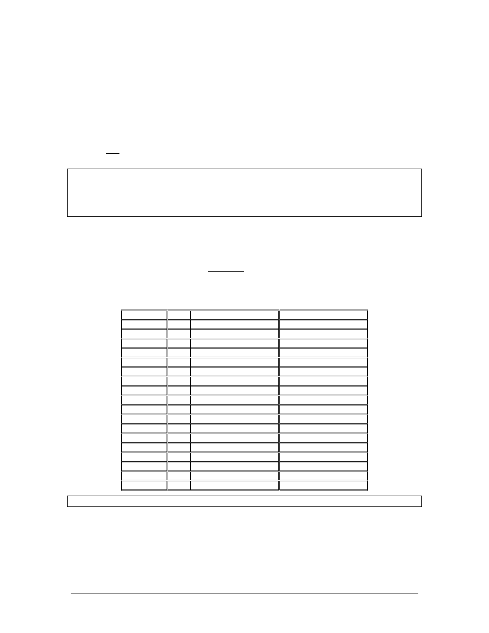
2.4.2.1
Differences with GMA340 connector
Connector
Pin
GMA340 Function
PMA450 Function
J1
3
COM 3
No Connection
J1
4
COM 3
No Connection
J1
5
COM 3
No Connection
J1
6
COM 3
No Connection
J1
16
MASQ Inhibit
No Connection
J1
23
COM 3 Speaker Load
AUX Audio Input
J1
24
COM 3 Speaker Load
CNX80 Inhibit
J1
25
COM Speaker Load
No Connection
J1
26
COM Speaker Load
No Connection
J1
27
COM Speaker Load
No Connection
J1
28
COM Speaker Load
No Connection
J1
29
No Connection
Unswitched #3
J2
15
High Music Gain Select
Unswitched #4
J2
17
8Ω Speaker Select
No Connection
J2
18
No Connection
Aux Enable Output
J2
19
Tone Enable
PA Enable
J2
29
Failsafe warn
No Connection
J2
30
Com TX Mute
MKR High Sense control
Table 2-2 GMA340–PMA450 connector differences
Installations where the external marker outputs are connected to a Sandel 3308 Navigation Display will
require additional loading resistors. Refer to the Sandel installation data for more information.