Section iii operation, Scope, Power and fail safe (1) – PS Engineering PMA450 Installation Manual User Manual
Page 21
PS Engineering
PMA450 Audio Selector Panel and Intercom System
Installation and Operator’s Manual
200-450-0000
Page 3-1
Rev. 3, November 2014
Section III OPERATION
3.1
SCOPE
This section provides detailed operating instructions for the PS Engineering PMA450, Audio Selector Pan-
el/Marker Beacon Receiver/Intercom Systems. Please read it carefully before using the equipment so that
you can take full advantage of its capabilities.
This section is divided into sections covering the basic operating areas of the PMA450 systems. They are
Communications Transceiver Selection, Audio Selector, Intercom, Marker Beacon Receiver and special
functions, including the Bluetooth® functionality in the PMA450.
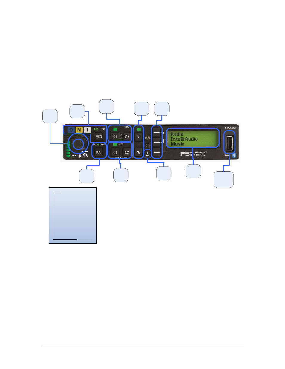
Figure 3-1 PMA450 Operating Controls
3.2
Power and Fail Safe (1)
Unit power is turned on and off by pushing the volume knob (1). There is a built in delay to prevent acci-
dental shut off while adjusting the intercom volume in turbulent conditions. In the
OFF
or "EMG" position,
the pilot headset is connected directly to Com 1 as well as unswitched input #1. This allows communication
capability regardless of unit condition. Any time power is removed or turned
OFF
, the audio selector will
revert to fail-safe mode.
The power switch controls all audio selector panel functions, intercom and marker beacon receiver. All
transceiver and receiver selections will be remembered and return to the last state when turned on.
1
Unit power is turned on and off by pushing the volume knob (1). There is a built in delay to prevent
accidental turn off.
1
2
3
4
5
6
8
9
7
1. Volume on off
2. Transmit Selection
3. Receiver Selection
4. Nav selection
5. Line select buttons
6. LCD Display
7. Speaker Selection
8. Intercom
9. Marker
10. USB Power Port
10