Appendix c – j1 connector interconnect – PS Engineering PDA360EX Installation Manual User Manual
Page 40
PS Engineering Inc. ®
PAR100EX Audio Selector Panel and Intercom System
Installation and Operator’s Manual
200-760-0000
Appendix C
Rev. 12, Jan. 2014
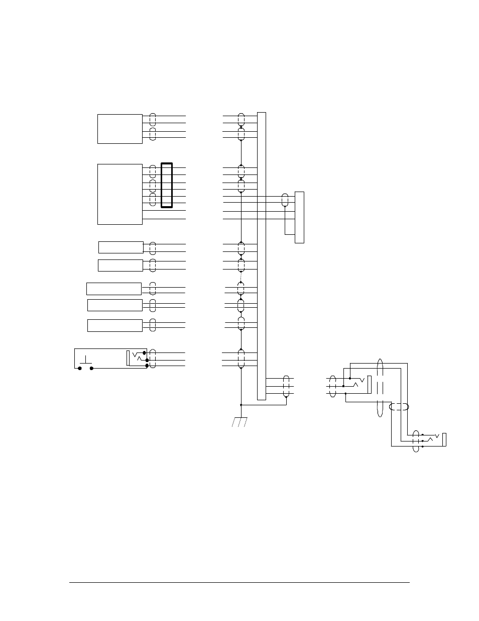
Appendix C – J1 Connector Interconnect
Com 1 Audio Hi
Com 1 Mic Key
Com 1 Audio Lo
Primary
Communications
Transceiver
Secondary
Communications
Transceiver
(R760)
Nav 1 Audio Hi
Nav 1 Audio Lo
VHF Nav 1
Nav 2 Audio Hi
Nav 2 Audio Lo
VHF Nav 2
Unswitched Input #1 Hi
Unswitched Audio Lo
Unswitched Audio #1
Unswitched Input #2 Hi
Unswitched Audio Lo
Unswitched Audio #2
Pilot Mic Audio Hi
Pilot Mic PTT
Pilot Mic Lo
9
10
11
12
Com 1 Mic Audio Hi
Com 2 Audio Hi
Com 2 Mic Key
Com 2 Audio Lo
13
14
15
30
Com 2 Mic Audio Hi
17
18
19
20
29
17
31
32
44
43
33
34
35
30
42
11
Notes:
1. All shields should be grounded at audio panel only.
Other end remains floating.
2. All Power, and Ground wires shall be #22 gage wire
Lighting #22 AWG, other wires minimum #24 AWG
3. All mic and headphone jacks must be isolated from ground.
4. All shielded wires must be MIL 22750 or 27500.
5. Unswitched inputs are always presented to
crew headphones, regardless of SPR switch or PTT.
Unswitched #3 is adjustable
6. All connections for R760 Radio shown for convenience.
Shown as COM 2. Can be connected as COM 1. See 2.5.2.
7. Ferrite RFI Supressor, 507-000-0065 must be installed
on radio audio and data lines. See Sect. 2.14.1
Pilot PTT
PAR100EX Connector, J1 (Sub-D 44-pin, male on tray)
Unswitched Input #3 Hi
Unswitched Audio Lo
Unswitched Audio #3
29
S
e
e
N
o
te
5
Pass. Phones (R)
Pass Phones (L)
Pass. Phones Lo
Pass. 1 PhonesJack
Pass. 2 Phones Jack
22
41
40
42
RS232 TX
RS232 RX
14
12
1
7
2
5
Radio Power
Radio Ground
9
11
J2
See Note 6
Ferrite RFI Supressor
(507-000-0065) see Note 7