R760rem antenna connection, R760rem, Ntenna connection – PS Engineering PDA360EX Installation Manual User Manual
Page 12
PS Engineering Inc. ®
PAR100EX Audio Selector Panel and Intercom System
Installation and Operator’s Manual
200-760-0000
Page 2-5
Rev. 12, Jan. 2014
If the M760REM is used as COM 1, the PAR100EX can fail-safe to it, because it is divided internally as
audio panel and COM control. In addition, the M760REM power supply is provided by an independent
circuit breaker and power supply in the PAR100EX. See § 3.2 for operational information.
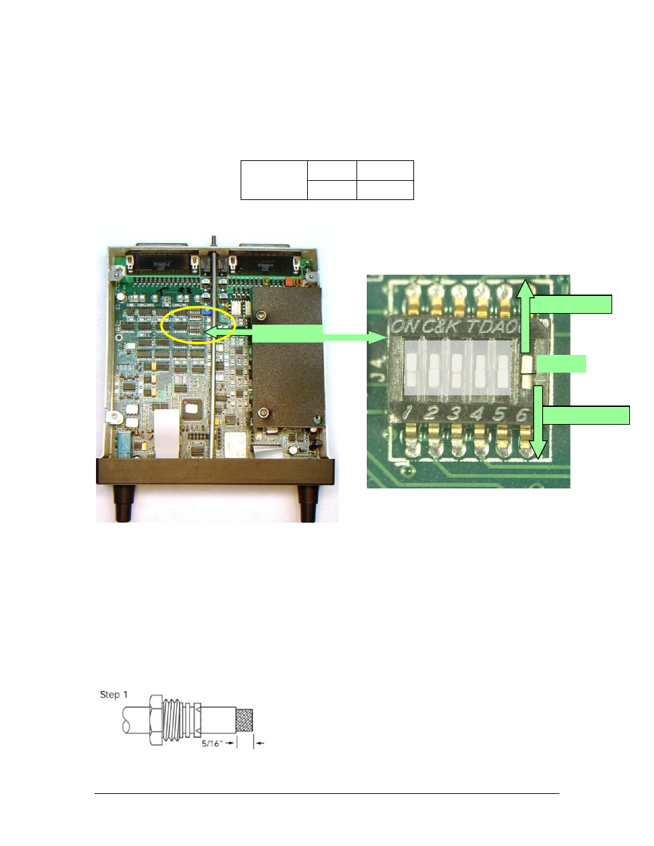
As shipped from the factory, the PAR100EX is configured to use the M760REM as COM 2. The
PAR100EX must be reconfigured at installation to be used as COM 2, by removing the top cover, and
placing the DIP switches as shown.
COM 1
OFF
J4 Switch 6
COM 2
ON
Table 2-2 Radio Selection
Figure 2-2 DIP Switch Locations
Figure 2-3 Switch J4, SW 6 location
Refer to § 2.8 for disassembly instructions.
When properly selected, the PAR100EX LCD display will read either COM 1, or COM 2.
2.5.3
R760REM Antenna connection
The VHF Com radio uses a solder/crimp BNC connector, Amphenol 31-2. Assemble the RF connector as
shown:
SW 6
ON for COM 2
OFF for COM 1
J4 Location