3 setup of satellite i/o box to master i/o box 12, Hapter 2.3.3 “setup of satellite i/o box to, 3 setup of satellite i/o box to master i/o box – Casio IT-2000 User Manual
Page 12
12
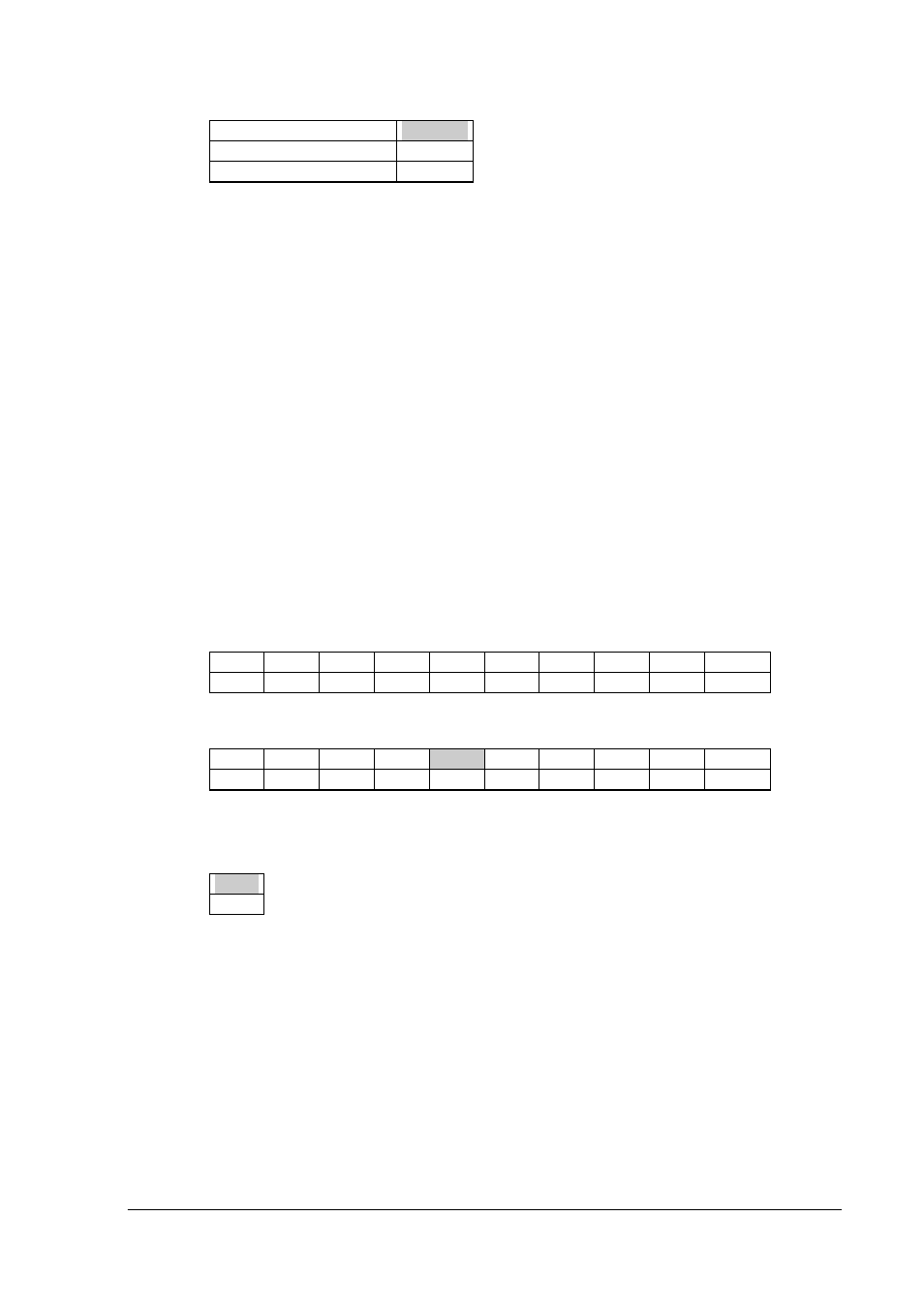
Power SCSI termination
10
Supplies power
ON
Does not supply power
OFF
Connect the first I/O Box and PC with the SCSI cable.
Then connect the SCSI connector of the I/O Box connected to the PC to the SCSI connector of
the other I/O Box via the SCSI cable. Connect the remaining I/O Boxes so that the one with the
terminator setting becomes to the last under daisy-chain connection.
Select a suitable cable that matches the shape of the connector on the PC side to connect the PC
and the first I/O Box.
2.3.3 Setup of Satellite I/O Box to Master I/O Box
Note that the DIP switch settings on Master I/O Box and on Satellite I/O Box differ.
DIP switch settings of the Master I/O Box
These settings are the same as stated in Chapter 2.3.2, "Setup of Master I/O Box" except
that the no.5 should be set to OFF.
1
2
3
4
5
6
7
8
9
10
ON
OFF
OFF
OFF
OFF
OFF
OFF
OFF
ON
OFF
DIP switch settings of the Satellite I/O Box
1
2
3
4
5
6
7
8
9
10
ON
OFF
ON
OFF
OFF
OFF
ON
ON
ON
ON
Set DIP switch no.5 to ON (i.e. setting as a terminator) if the C-OUT terminal is not
connected to another Satellite I/O Box to be daisy-chained.
5
ON
The above setup example assumes that the RS-232C baud rate is 115200 bps. If modifying this
setup, refer to Chapter 2.3.1, "Setup of Satellite I/O Box".
Connect the first Master I/O Box and PC with SCSI cable.
Then connect the C-OUT terminal of the Master I/O Box connected to the PC to the
C-IN terminal of the other Satellite I/O Box via the RS-422 cable. Connect the remaining I/O
Boxes so that the one with the terminator setting becomes the last under daisy-chain
connection.