NORAC UC4+BC+JD7A User Manual
Page 37
34
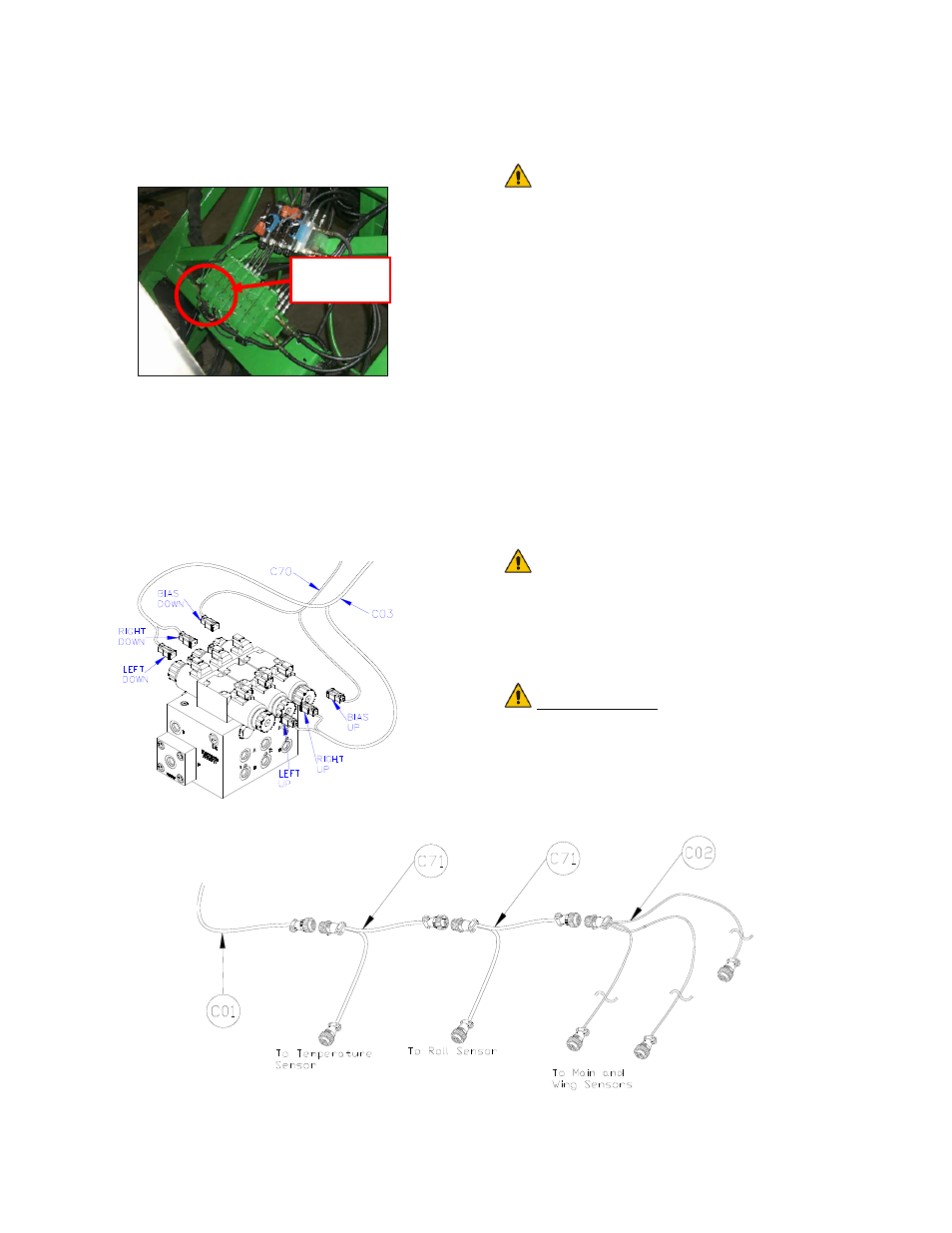
13. Connect the 4-pin square connector on the
roll control cable (C70) to the roll
connector on the JD harness (Figure 44).
Figure 44: JD Roll Connector
14. Install the 2-pin connectors from C03 onto
each NORAC valve as shown in Figure 45.
The connectors are marked RIGHT UP,
LEFT UP, RIGHT DOWN and LEFT
DOWN. Cables labeled with UP go on the
same side as the hydraulic hoses.
Figure 45: Valve Cable Connections
15. Connect the 2-pin connectors on C70 to
the 3
rd
station of the valve block.
The 2-pin connector labeled BIAS
UP connects to the same side of the
valve block as the hoses.
16. Connect temperature sensor cable (C71) as
shown in Figure 46.
17. Connect the Sensor Roll Bias cable (C71) to
the trunk cable (C01). Route cable C71 to
the roll sensor.
18. Connect the sensor branch cable (C02) to
the free connector on cable C71 (Figure
46).
19. Route the sensor branch cable (C02) to the
wing and main sensors. Follow existing
cables and/or hydraulic lines along the boom.
Route the main lift cable through the
main lift mounting bracket tube to
provide additional cable protection.
20. Cable-tie the installed cables every 12
inches.
IMPORTANT:
Provide enough slack in all cables to
account for the movement of the main
section, parallel lift, and FOLDING boom
movement.
Figure 46: Cable Configurations: C01, C71 and C02
4-pin Roll
Connector