NORAC UC4+BC+JD7A User Manual
Page 28
25
A B C
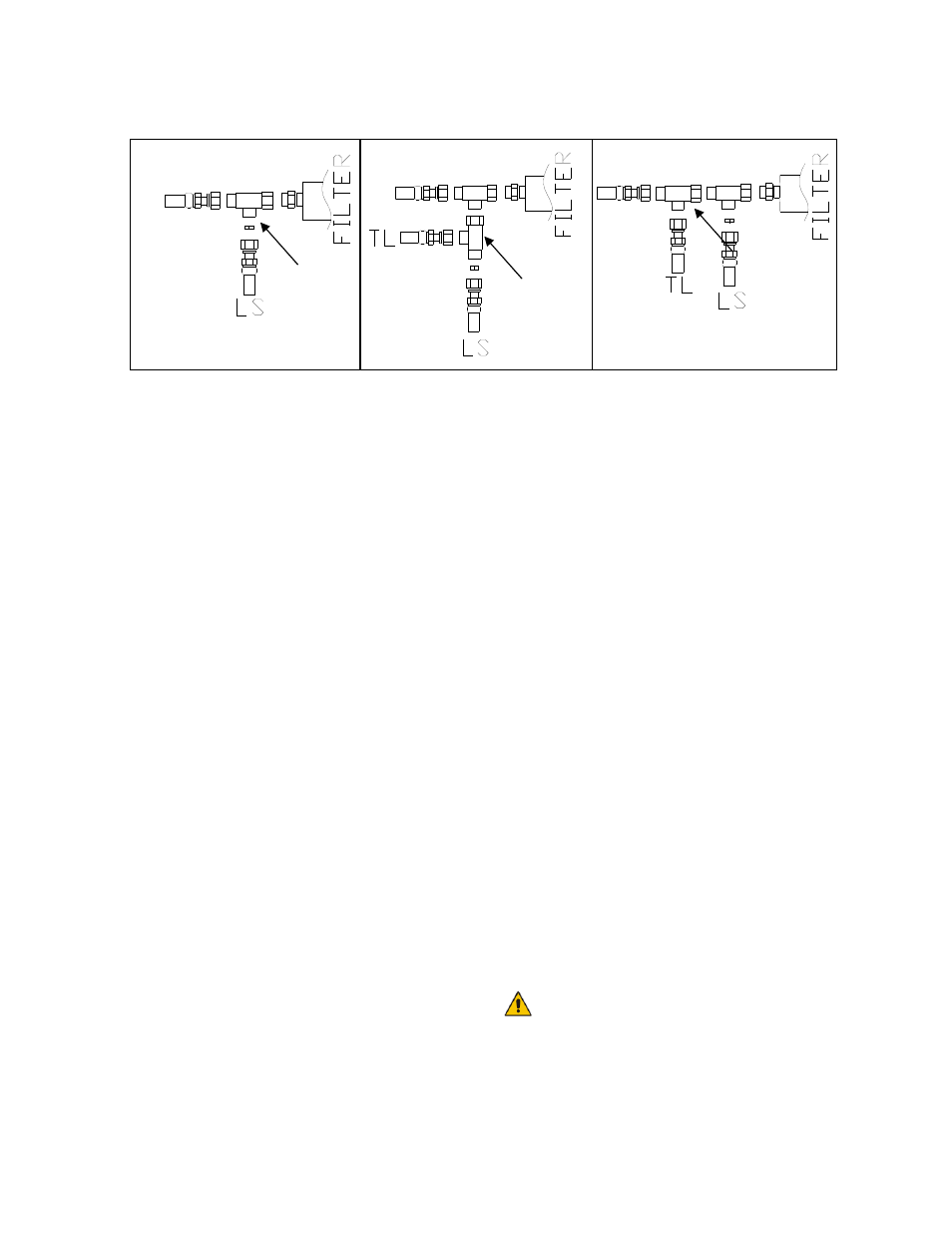
Figure 33: Secondary Tank Line Install
(Load Sense = LS, Tank Line = TL)
7. Route the other end of hose H71 to the
Norac valve block, following existing hoses.
Connect it to the 6FORXR-6MORT tee
fitting (F10) in the “T” port of the NORAC
valve block.
8. Tee the hoses, H02 (“P” and “T” lines), into
the ports on the sprayer valve block with
6FORXR-6MORT fittings (F03) and 6MB-
6MOR fittings (F05). The elbow fittings
currently in place must be replaced by the
6MB-6MOR fitting (F05). The “P” and “T”
lines are located on the left side of the John
Deere valve block.
9. Connect the free end of hose H02, installed
at the JD “P” port, to the tee on the “P”
port of the NORAC valve block.
10. Connect the free end of hose H02 installed
on the “T” port of the JD block to the tee
(F10) installed in the “T” port of the
NORAC block.
11. Connect hose H74 to the Load Sense (“S”)
port on the valve block.
12. Connect one end of the hydraulic hoses
(H76) to the Norac 3
rd
station valve block’s
“A” and “B” ports.
13. Route the other end of the hoses to the roll
cylinder previously installed.
14. Attach the hose connected to the “B” port
of the valve block to the rod end of the
cylinder.
15. Connect the hose connected to the “A”
port of the valve block to the cap end of the
cylinder.
16. The existing hoses that run to the boom tilt
cylinders should be disconnected from the
sprayer valve block and reconnected to the
NORAC valve block.
a)
The “raise” lines must be connected to
the "B" ports of the NORAC valve block.
The ports on the sprayer block must
then be capped with 4MBP plugs (F09).
b)
The "A" ports of the NORAC block
must be connected to the “lower” lines
of the cylinders. The ports on the
sprayer block must then be capped with
F09.
Most John Deere Sprayers have
orifices in the "A" and "B" lines of
the boom tilt cylinders. To remove
the orifices you must remove the