NORAC UC4+BC+JD7A User Manual
Page 26
23
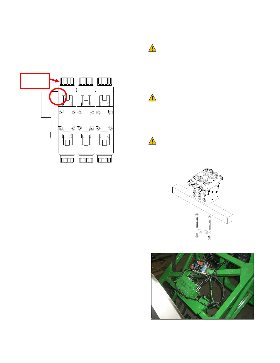
5. Install the setscrew (F11) into the Sense
Line Bleed Orifice location. Ensure the
setscrew is threaded entirely into the hole
and tightened to 35-40 in-lbs to ensure a
tight seal. Reinstall the plug and tighten to
35-40 in-lbs.
Figure 28: Load Sense Bleed Orifice
Location on Top of Block
10. Mount the NORAC valve (V01) on the
sprayer using the valve mounting bracket
(B10).
11. Thread a nut onto the short threads of each
of the threaded studs.
12. As shown in Figure 29, screw the short
side of the threaded rods into the bottom of
the valve block and tighten the hex nuts tight
to the valve block.
13. Place the valve block onto a frame member,
with the studs extending to the other side of
the member.
14. Slide the flat bar from the bracket over the
studs and install a spring washer and nut
onto each of the studs to hold the bracket in
place.
15. Tighten the two nuts so the valve block is
held on tight and cannot move.
16. Cut excess off of the rods, if necessary.
If you wish to use bolts, the bolts
should thread into the valve block at
least 3/8". The valve mounting holes
are drilled and tapped 3/8 NC-1"
deep. The rule of thumb for bolt
length is 1-1/2" longer than the tube
size.
The recommended location for the
valve is on the angled cross tube of
the parallel linkage on the sprayer.
Orient the valve block so the "A" and
"B" ports face towards the boom
(Figure 30).
You must ensure no hydraulic
components will interfere with any
sprayer parts or be pulled tight at
any time.
Figure 29: Valve Mounting Location
Figure 30: Valve Mounting Example
Remove
this coil