Anti-roll bar adjustment chart – NM Engineering 258846 User Manual
Page 2
NM Engineering ∞ 3300 Corte Malpaso, Camarillo, CA 93012 ∞ 805.388.7171 ∞ 805.388.0030 FAX
engineer@nm-
eng.com ∞ www.nm-eng.com
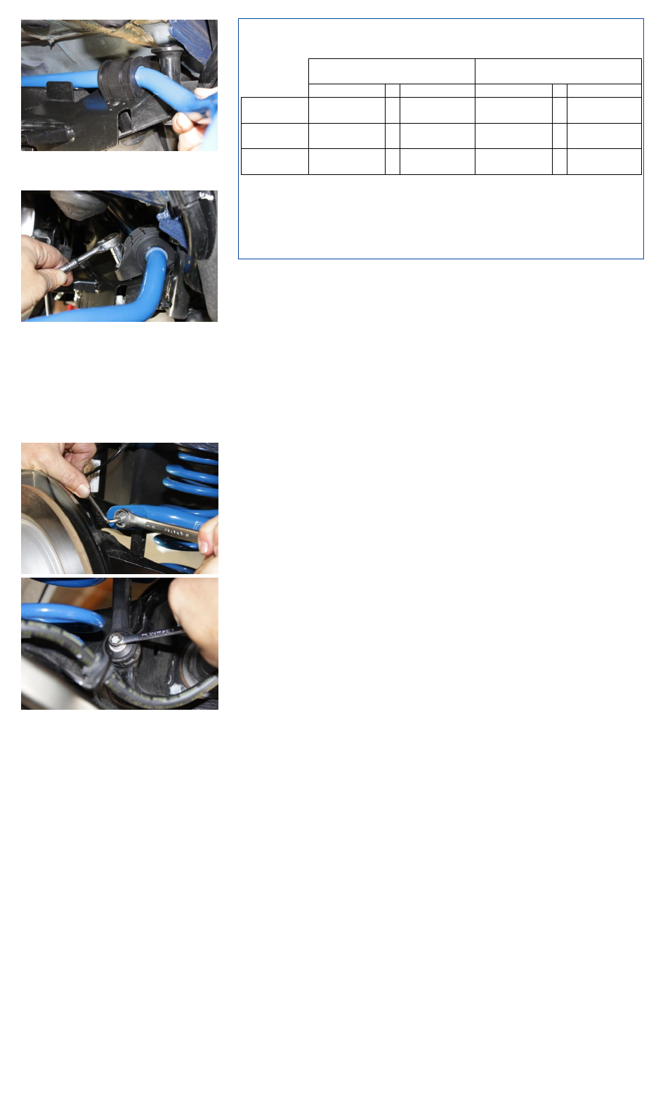
15. Apply supplied grease to inside of supplied
urethane bushings and install on NM anti-roll
bar.
16. Install original bushing clamps and bolts.
Torque to 34 Nm (25 ft-lbs).
17. Re-mount sub-frame to uni-body with the [4]
original bolts and torque to 100Nm (74 ft-lbs).
NOTE
: Make sure brake lines re-attach to
their support mounts on the uni-body.
18. Re-install
rear
springs
in
reverse
of
disassembly. Torque lower shock mount bolt
to 100Nm (74 ft-lbs).
19. Attach upper end-links to NM anti-roll bar
using original nuts. Torque to 48Nm (35 ft-
lbs). Then tighten lower end-link bolt. Torque
to 34Nm (25 ft.-lbs.). See adjustment chart
for hole position information.
20. Mount rear wheels. For factory wheels
ONLY, torque lug bolts to 140Nm (103 ft-lbs).
For aftermarket wheels, contact wheel
manufacturer for proper torque specifications.
21. Double-check complete installation and test
drive carefully.
©2015 NM Engineering, a division of Automotive Performance
Systems, Inc.
All rights reserved. Reproduction in whole or in part is prohibited.
DOC. NM.258846 Rev. 01.13.15
Anti-Roll Bar Adjustment Chart
LEFT-SIDE END-LINK
POSITION
RIGHT-SIDE END-LINK
POSITION
Rear Hole
Front Hole
Rear Hole
Front Hole
Setting 1
[Softest]
X
X
Setting 2
X
X
Setting 3
[Stiffest]
X
X
Recommended adjustment procedure:
Start with softest setting and drive car on familiar road. Adjust bar to next stiffer
setting if further reduction of understeer is needed. Continue to adjust until
proper balance suited to your motoring style is achieved.