Sway bar adjustment chart – NM Engineering 258856 User Manual
Page 2
NM Engineering ∞ 3300 Corte Malpaso, Camarillo, CA 93012 ∞ 805.388.7171 ∞ 805.388.0030 FAX
[email protected] ∞ www.nm-eng.com
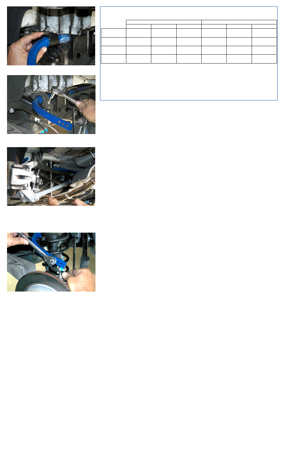
13. Apply supplied grease to inside of supplied bushings and
install on the inside of stop washer on NM anti-roll bar.
14. Install billet aluminum clamps over bushings and bolt to sub-
frame using supplied M8 x 25mm bolts. Torque to 33 Nm (25
ft-lbs).
15. Reinstall sub-frame mounting bolts on right-side and torque all
[4] bolts to 100 Nm (74 ft-lbs).
16. Install rear shocks in reverse of disassembly. Torque top
shock mount bolts to 56 Nm (41 ft-lbs) and torque lower shock
mount bolt to 165 Nm (121 ft-lbs). Reattach brake line and
ABS wire on each side.
17. Attach end links to NM anti-roll bar using original nuts. Torque
to 30 Nm (22 ft-lbs). See adjustment chart for hole mounting
information.
18. Mount rear wheels. For factory wheels ONLY, torque lug bolts
to 140Nm (103 ft-lbs). For aftermarket wheels, contact wheel
manufacturer for proper torque specifications.
19. Double-check complete installation and test drive carefully.
©2009 NM Engineering, a division of Automotive Performance Systems, Inc.
All rights reserved. Reproduction in whole or in part is prohibited.
DOC. NM.258856 Rev. 01.13.09
Sway Bar Adjustment Chart
LEFT-SIDE END-LINK POSITION
RIGHT-SIDE END-LINK POSITION
Rear Hole
Middle Hole
Front Hole
Rear Hole
Middle Hole
Front Hole
Setting 1
[Softest]
X X
Setting 2
X X
Setting 3
X X
Setting 4
[Stiffest]
X X
Recommended adjustment procedure:
Start with softest setting and drive car on familiar road. Adjust bar to next stiffer setting if further reduction
of understeer is needed. Continue to adjust until proper balance suited to your motoring style is
achieved.