Synth channel controls – Muse Research Receptor VIP manual v1.1 User Manual
Page 25
25
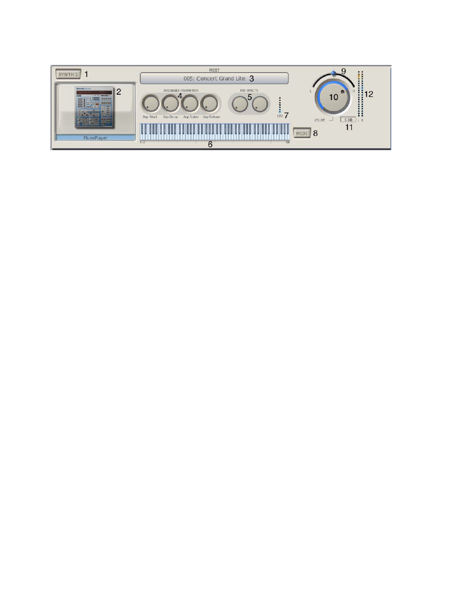
Synth Channel Controls
Descriptions of all the Synth Channel controls are as follows:
1. Channel Solo Switch: Solos this channel and mutes all others when pressed / lit.
2. Synth Graphical Editor: Shows a small picture of the synth loaded into that channel. Click on
the picture to open up the graphical editor for that channel.
3. Preset selector: Drop-down menu that lets you browse and select any of the presets in the
currently selected TAg or BANK.
4. Assignable Parameters: These two knobs are "assignable parameters" which are the first four
parameters that you assign using the MIDI Learn function.
Tip: You can move all the knobs in the RECEPTOR VIP GUI by clicking and dragging the knob in a
circular fashion, or by simply resting the mouse indicator on the knob and using your mouse scroll
wheel to rotate the knob.
5. MIX Effects: These four knobs control the amount that is "sent" to the two MIX effects,
assuming they are in SEND mode.
6. Keyboard Range: Shows the current playable range of this particular synth. Allows you to see
splits or assigned ranges easily. Click on the left hand side of the keyboard to change the lower
range, and click on the right hand side of the keybaord to change the top range.
7. CPU indicator: This meter shows the relative load on the CPU in real time from this particular
plugin. Playing more notes at one time will increase the CPU load.
8. MIDI Button: Lets you open up the MIDI FILTER page. The MIDI Filter page lets you re-assign
MIDI channels, adjust the transposition of the channel, change the note range and velocity range of
the plugin, and activates the MIDI monitor that displays all the incoming MIDI information.
9. Channel Output Pan Control: Adjusts the output between the left and right channels.
10. Channel Output Volume Control: Adjusts the relative level of this channel’s output.
11 Output dB readout: The output level from nominal is indicated numerically in decibels in the
small display to the right of the volume control to allow precise volume settings (you can use your
mouse scroll wheel for this).
12. Channel Level Meters: These meters indicate the output level coming from this channel.
Reduce the output volume control if the red segments at the top of the meter illuminate. Clipping
conditions will cause the top-most segment to glow red and stay that way until reset with a click.