Milwaukee Tool 2260-21NST User Manual
Page 14
12
M12 160x120 Thermal Imager Operator’s Manual
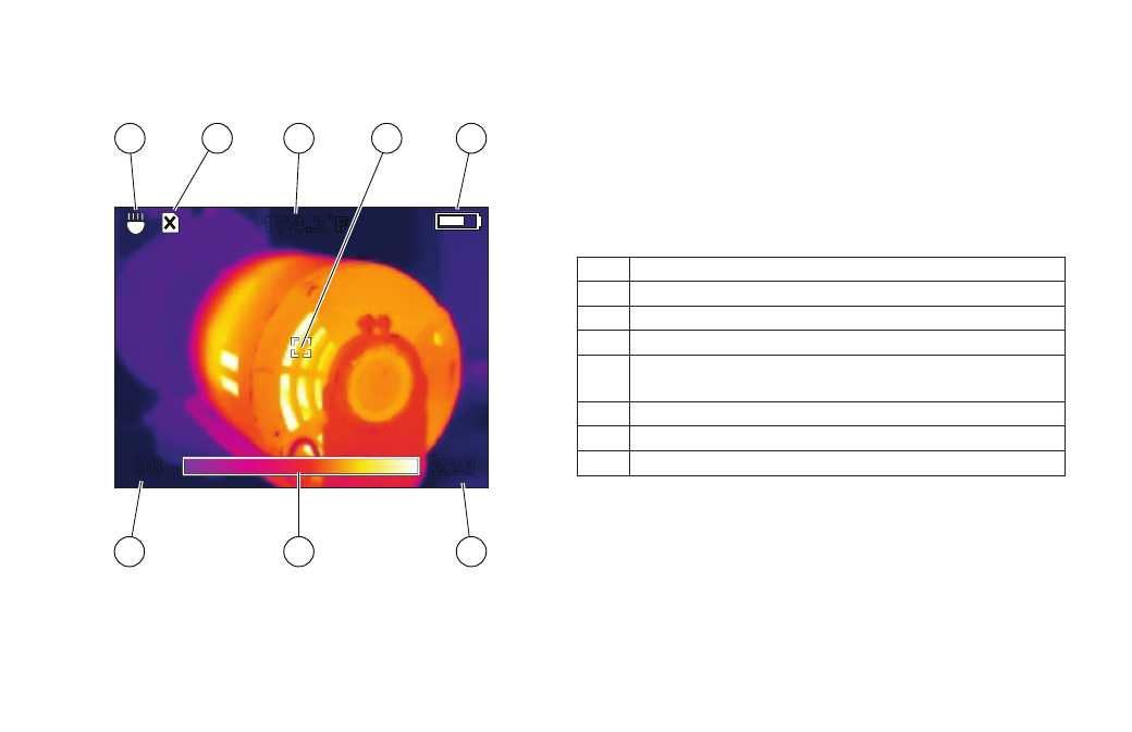
Figure 5. Elements of the Thermal Image Display
226
174.3˚F
98
7
6
5
8
4
1
2
3
Table 4. Explanation of Display Elements
1
LED flashlight is on
2
SD card is not installed (you cannot save images)
3
Target temperature
4
Target
5
Battery charge indicator (more white = more
charge remaining)
6
Upper limit of range
7
Picture of color palette in use ("Iron" is shown)
8
Lower limit of range
This manual is related to the following products: