Milwaukee Tool 2212-20 User Manual
Page 3
4
5
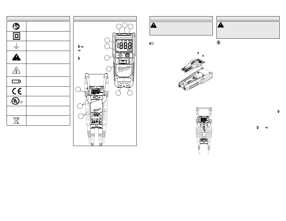
Loading/Changing the Batteries
Replace batteries when the Low Battery indicator
is displayed.
1. Press the Power ON/OFF button to turn off the
tester. Disconnect the test leads.
2. Unscrew and
remove battery
door.
3. Insert two (2)
AAA batteries,
according to the
polarity marked
in the battery
compartment
4. Close the battery
door and tighten
two (2) screws
securely.
Installing/Removing the Belt Clip
The belt clip can be removed/installed into the
accessory bay. Line up the belt clip and secure
with the accessory bay screw.
Storage
To store the leadwires when not in
use, rotate the belt clip 90°. Wrap
the leadwires around the body of the
tester. Rotate the belt clip down to
hold the leadwires in place.
Probe Tip Sleeves
Measurement Category and Voltage Rating of the
Test Leads:
Probe Tip Sleeves ON:
Cat IV, 600V / CAT III 1000V
Probe Tip Sleeves OFF:
Cat II 1000V
To remove the probe tip sleeves:
1. Disconnect the test leads from the tester.
2. Grasp the probe fi rmly in one hand.
3. Hold the probe tip sleeve fi rmly with the other
hand.
4. Pull to remove the probe tip sleeve to expose
more of the probe tip.
5. Push probe tip sleeve back onto probe tip when
not in use.
SYMBOLOGY
Read Operator’s Manual
Double insulation
Earth
Danger, Warning, or Caution
- Consult the operators
manual for additional safety
information.
Risk of electrical shock - To
avoid electric shock, remove
test leads before opening bat-
tery door
Battery compartment
European Conformity Mark
Underwriters Laboratories, Inc.,
United States and Canada
Cat IV
Classifi cation of transient
overvoltages, based on
nominal line voltage to earth.
Do not dispose of this product
as unsorted municipal waste.
ASSEMBLY
WARNING
To avoid an electrical
hazard, turn the tester OFF and disconnect the
test leads before replacing batteries.
OPERATION
LCD Backlight
The LCD backlight will turn off about 20 seconds
after Power-ON is pressed. The backlight will be
triggered on every time a voltage is measured
higher than 5 V AC/DC. It will not reactivate under
resistance or continuity measurements.
LED Worklight
Press the Worklight Button to turn the LED on and
off. The worklight will turn off automatically after
about 1 minute. It is not necessary to turn on the
Tester to use the worklight.
Making a Measurement
Auto-Function
The tester is designed to auto range at all times.
With Auto Ranging, the tool will automatically select
the range with the best resolution
The Tester automatically switches from Voltage AC/
DC measurement to Continuity when no voltage
is present. The tool will automatically identify VAC
from VDC and will indicate which on the display.
Hazard Voltage Warning
If measured voltage is over AC/DC 35 V, the
Indicator LED will be lit RED and the buzzer will
sound with steady, intermittent beeps (B_B_B).
Over-Range Indication
If measured voltage exceeds the measuring range
(over approximately 600V), the and Indicator
LEDs fl ash rapidly, alternating RED and YELLOW.
The buzzer will sound with bursts of three repeating
beeps (BBB_BBB_BBB).
Auto Off Function
The tester is automatically powered off in about
10 minutes after Power-ON is pressed, preceded
by two beeps. To continue use, press the Power-
ON again after shut-off. If the display is still blank,
replace the batteries.
WARNING
Only use Milwaukee test
leads with the MILWAUKEE Tester. Inspect
test leads for continuity before each use. Do
not use if the readings are high or noisy.
FUNCTIONAL DESCRIPTION
1. Display
2. Worklight button
3. Power button
4. Function switch
(Cat.No. 2213 only)
5. COM Terminal input
6. Ω Terminal input
7. Indicator
8. LED Worklight
9. Indicator
10. Probe storage
11. Grips
12. Accessory bay
5
6
8
9
7
10
12
11
4
2
1
3