Milwaukee Tool 6185-20 User Manual
Page 4
6
7
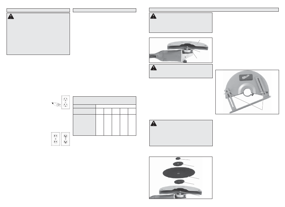
Grounded Tools: Tools with Three Prong Plugs
Tools marked “Grounding Required” have a three
wire cord and three prong grounding plug. The
plug must be connected to a properly grounded
outlet (See Figure A). If the tool should electrically
malfunction or break down, grounding provides a
low resistance path to carry electricity away from
the user, reducing the risk of electric shock.
The grounding prong in the plug is connected
through the green wire inside the cord to the
grounding system in the tool. The green wire in the
cord must be the only wire connected to the tool's
grounding system and must never be attached to
an electrically “live” terminal.
Your tool must be plugged into an
appropriate outlet, properly installed
and grounded in accordance with
all codes and ordinances. The plug
and outlet should look like those in
Figure A.
Double Insulated Tools:
Tools with Two Prong Plugs
Tools marked “Double Insulated” do not require
grounding. They have a special double insulation
system which satisfi es OSHA requirements and
complies with the applicable standards of Underwrit-
ers Laboratories, Inc., the Cana-
dian Standard Association and the
National Electrical Code. Double
Insulated tools may be used in ei-
ther of the 120 volt outlets shown in
Figures B and C.
Fig. B Fig. C
Fig. A
GROUNDING
WARNING
Improperly connecting the
grounding wire can result in the risk of elec-
tric shock. Check with a qualifi ed electrician
if you are in doubt as to whether the outlet is
properly grounded. Do not modify the plug
provided with the tool. Never remove the
grounding prong from the plug. Do not use
the tool if the cord or plug is damaged. If
damaged, have it repaired by a MILWAUKEE
service facility before use. If the plug will not
fi t the outlet, have a proper outlet installed by
a qualifi ed electrician.
ASSEMBLY
WARNING
To reduce the risk of injury,
always unplug tool before attaching or remov-
ing accessories or making adjustments. Use
only specifi cally recommended accessories.
Others may be hazardous.
Grounded tools require a three wire extension
cord. Double insulated tools can use either a two
or three wire extension cord. As the distance from
the supply outlet increases, you must use a heavier
gauge extension cord. Using extension cords with
inadequately sized wire causes a serious drop in
voltage, resulting in loss of power and possible tool
damage. Refer to the table shown to determine the
required minimum wire size.
The smaller the gauge number of the wire, the
greater the capacity of the cord. For example, a 14
gauge cord can carry a higher current than a 16
gauge cord. When using more than one extension
cord to make up the total length, be sure each cord
contains at least the minimum wire size required.
If you are using one extension cord for more than
one tool, add the nameplate amperes and use the
sum to determine the required minimum wire size.
Guidelines for Using Extension Cords
• If you are using an extension cord outdoors, be
sure it is marked with the suffi x “W-A” (“W” in Cana-
da) to indicate that it is acceptable for outdoor use.
• Be sure your extension cord is properly wired
and in good electrical condition. Always replace a
damaged extension cord or have it repaired by a
qualifi ed person before using it.
• Protect your extension cords from sharp objects,
excessive heat and damp or wet areas.
READ AND SAVE ALL
INSTRUCTIONS FOR FUTURE USE.
* Based on limiting the line voltage drop to fi ve volts at
150% of the rated amperes.
EXTENSION CORDS
Recommended Minimum Wire Gauge
For Extension Cords*
Extension Cord Length
Nameplate
Amperes
25'
50'
75'
100'
150'
0 - 2.0
2.1 - 3.4
3.5 - 5.0
5.1 - 7.0
7.1 - 12.0
12.1 - 16.0
16.1 - 20.0
18
18
18
18
16
14
12
18
18
18
16
14
12
10
18
18
16
14
12
10
--
18
16
14
12
10
--
--
16
14
12
12
--
--
--
Installing, Adjusting, and Removing the Guard
1. To install the guard, unplug the tool and place it
on its side on a level surface. Line up the tabs
with the tab slots. Then press the guard down
onto the tool.
2. Position the guard in the location which offers best
control and guard protection.
3. Tighten the bolt with a 5/16" hex wrench to
secure the guard to the tool.
4. To remove the guard, unplug tool and place it
on its side on a level surface. Remove the shoe
and any accessories from spindle. Loosen the
bolt with a 5/16" hex wrench. Line up the tabs
with the tab slots and lift the guard straight up
and away from the tool.
Installing and Removing Cut-Off Wheels
Before operating the tool, make sure the wheel is in good
condition as described (see “Specifi c Safety Rules”).
1. To install cut-off wheels, place tool on a fi rm
surface with the guard surface facing up.
2. Remove the shoe (see "Installing and Removing
Shoe").
3. Slide the inner fl ange, cut-off wheel, outer fl ange,
and fl ange nut over the spindle. Be sure the
fl ange nut matches the wheel arbor hole size (1"
or 20 mm).
4. While holding in the spindle lock, tighten the nut
securely with the 5/16" hex wrench provided with
tool.
NOTE: Nut has a left hand thread. To tighten,
turn nut in a counterclockwise rotation.
5. To remove cut-off wheels, you must fi rst remove
the shoe. Then, while holding in the spindle
lock, loosen the nut with the 5/16" hex wrench
provided with tool. Remove the outer fl ange and
cut-off wheel.
WARNING
To reduce the risk of injury
when grinding, ALWAYS use the proper guard.
ALWAYS properly install the guard.
WARNING
To reduce the risk of injury,
use only the proper wheel made for this tool.
DO NOT USE ANY TYPE OF SAW BLADE. USE
ONLY TYPE “1” ABRASIVE AND DIAMOND
WHEELS. To ensure the wheel is properly se-
cured, always use the fl ange nut that matches
the wheel arbor hole size.
1. To install shoe assembly, loosen wing nuts on
shoe assembly.
2. Insert the fi rst bolt head into the hole in the guard.
Slide the bolt into the slot in the guard.
3. Angle shoe assembly, as shown, and place the
second bolt head into the guard.
4. Rotate the shoe until the second bolt head can
be moved into the slot in the guard.
5. Adjust shoe to proper height and tighten wing
nuts securely.
NOTE: The squares on the back of the bolt heads
must be aligned in the guard slots to ensure the
bolts do not extend into the guard and vibrate loose
during use.
6. To remove shoe assembly, loosen wing nuts and
slide shoe assembly so that both bolts can be
removed from holes in guard.
Installing and Removing Shoe
Inner fl ange
Cutting
wheel
Outer fl ange
Flange Nut
(1" or 20 mm)
Spindle
Fig. 2
Fig. 1
Bolt
Spindle
Guard
Wing nuts
Fig. 3