Milwaukee Tool 6742-20 Wiring 2003 User Manual
Wiring instructions, Single reduction pistol grip tools, Bulletin
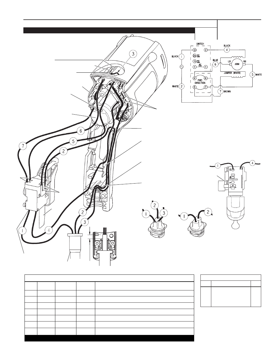
SINGLE REDUCTION PISTOL GRIP TOOLS
58-01-1800
DATE
Jan. 2003
MILWAUKEE ELECTRIC TOOL CORP. 13135 WEST LISBON RD. BROOKFIELD, WIS.
BULLETIN
WIRING INSTRUCTIONS
TITLE
Drwg. 3
Terminals, Connectors and 1 or 2 End Wire Preparation
Wire
Color
Origin or
Gauge
Wire
No.
Length
WIRING SPECIFICATIONS
BULK LEAD WIRE - BULLETIN NO. 58-01-0003
Grounding terminal
Green ground wire #3 connects
to male tab of grounding terminal.
Position terminal as shown.
(Grounded models only).
Route blue brush wire #6 and
white brush wire #5 through
wire traps over rear bearing
bore as shown.
FOR DOUBLE INSULATED TOOLS
DISREGARD GREEN GROUND WIRE #3
AND THE GROUNDING TERMINAL
Insert black wire #1
in the hole marked
2
↓
on the bottom
of the switch
Heat
Sink
For grounded tools with
3-wire quik-lok cords,
orientate the pin housing
assembly as shown and place
white wire #2 first into the
bottom of the handle portion of
the motor housing.
For double insulated tools
with 2-wire quik-lok cords,
orientate the blade housing
assembly as shown and place
white wire #2 first into the bottom
of the handle portion of the motor
housing.
In the main trap, route green ground wire #3
in the bottom followed by the white wire #2
and black wire #4 on the top.
Route black lead #4 through any of the three
traps on the tab of the motor housing and
insert into hole 2 on bottom of switch (Hole is
marked with a 2 on side of switch).
Route green ground wire #3 and
white wire #2 around the post in
the motor housing. Wires cannot
touch the heat sink of the switch.
Post
Rear bearing bore
Fixed cord
shown
Black wire #1 Black wire #4
If screw is
present
seat
screw
fully.
Bottom
view of
switch
1
Black
*
-----
*Component of cord set, pin hsg. assy. or blade hsg. assy.
2
White
*
-----
*Component of cord set, pin hsg. assy. or blade hsg. assy.
3
Green
*
-----
*Component of cord set, pin hsg. assy. or blade hsg. assy.
4
Black
**
-----
**Component of the brush card assembly.
5
White
**
-----
**Component of the brush card assembly.
6
Blue
**
-----
**Component of the brush card assembly.
7
Brown
**
-----
**Component of the brush card assembly.
Route green ground wire #3 and jumper wire (white)
in recessed area of brush card as shown.
.25 min.
SCHEMATIC
T2
T2
(T1)
TERMINAL DESCRIPTION
Part No.
Code
Qnty.
T1
23-74-0605
1
T2
23-74-1060
4
Jumper
Wire